3 |
|
|
|
|
|
|
|
| Assembly Instructions | ||
A1 |
| A2 |
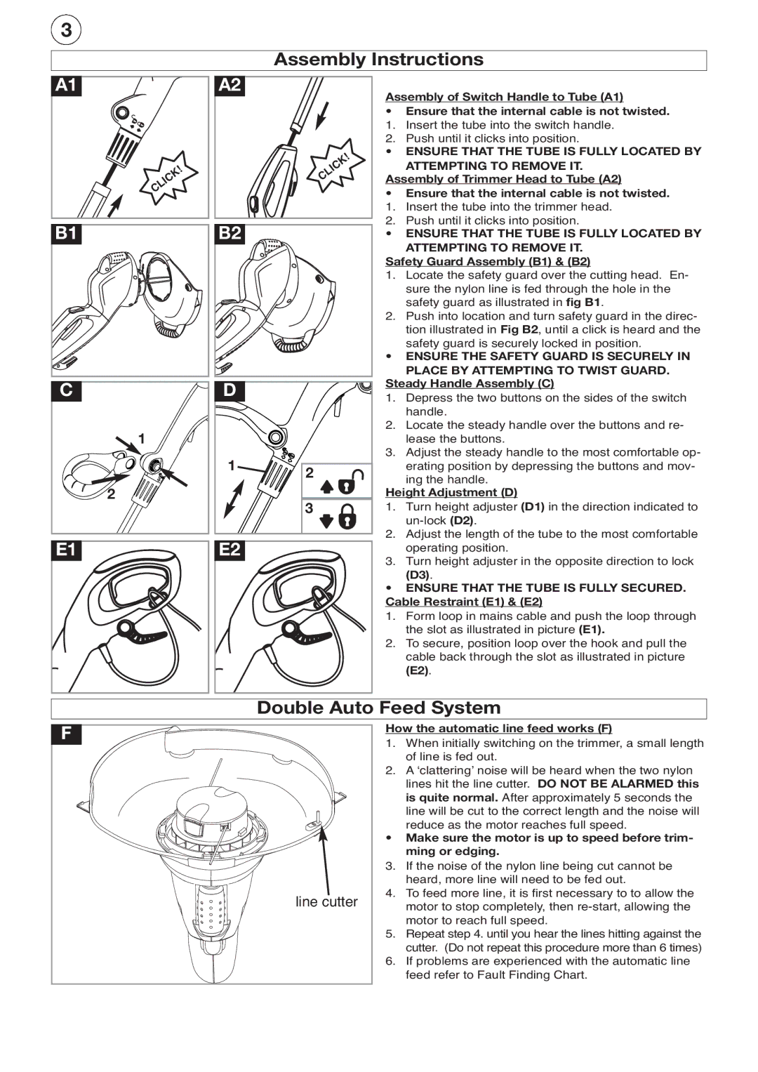
| Assembly of Switch Handle to Tube (A1) | |
|
|
|
| ||
|
|
|
| • | Ensure that the internal cable is not twisted. |
|
|
|
| 1. | Insert the tube into the switch handle. |
|
|
|
| 2. | Push until it clicks into position. |
|
|
| CLICK! | • | ENSURE THAT THE TUBE IS FULLY LOCATED BY |
| CLICK! |
|
| ATTEMPTING TO REMOVE IT. | |
|
| Assembly of Trimmer Head to Tube (A2) | |||
|
|
| |||
|
|
|
| • | Ensure that the internal cable is not twisted. |
|
|
|
| 1. | Insert the tube into the trimmer head. |
B1 |
| B2 |
| 2. | Push until it clicks into position. |
|
| • | ENSURE THAT THE TUBE IS FULLY LOCATED BY | ||
|
|
|
|
| ATTEMPTING TO REMOVE IT. |
|
|
|
| Safety Guard Assembly (B1) & (B2) | |
|
|
|
| 1. | Locate the safety guard over the cutting head. En- |
|
|
|
|
| sure the nylon line is fed through the hole in the |
|
|
|
|
| safety guard as illustrated in fig B1. |
|
|
|
| 2. | Push into location and turn safety guard in the direc- |
|
|
|
|
| tion illustrated in Fig B2, until a click is heard and the |
|
|
|
|
| safety guard is securely locked in position. |
|
|
|
| • | ENSURE THE SAFETY GUARD IS SECURELY IN |
|
|
|
|
| PLACE BY ATTEMPTING TO TWIST GUARD. |
C |
| D |
| Steady Handle Assembly (C) | |
|
| 1. | Depress the two buttons on the sides of the switch | ||
|
|
|
| ||
|
|
|
|
| handle. |
| 1 |
|
| 2. | Locate the steady handle over the buttons and re- |
|
|
|
| lease the buttons. | |
|
| 1 |
| 3. | Adjust the steady handle to the most comfortable op- |
|
| 2 |
| erating position by depressing the buttons and mov- | |
|
|
|
| ing the handle. | |
2 |
|
|
|
| |
|
| 3 | Height Adjustment (D) | ||
|
|
| 1. | Turn height adjuster (D1) in the direction indicated to | |
|
|
|
|
| |
E1 |
| E2 |
| 2. | Adjust the length of the tube to the most comfortable |
|
| 3. | operating position. | ||
|
|
|
| Turn height adjuster in the opposite direction to lock | |
|
|
|
|
| (D3). |
|
|
|
| • | ENSURE THAT THE TUBE IS FULLY SECURED. |
|
|
|
| Cable Restraint (E1) & (E2) | |
|
|
|
| 1. | Form loop in mains cable and push the loop through |
|
|
|
|
| the slot as illustrated in picture (E1). |
|
|
|
| 2. | To secure, position loop over the hook and pull the |
|
|
|
|
| cable back through the slot as illustrated in picture |
|
|
|
|
| (E2). |
|
|
| Double Auto Feed System | ||
F |
|
|
| How the automatic line feed works (F) | |
|
|
| 1. | When initially switching on the trimmer, a small length | |
|
|
|
| ||
|
|
|
|
| of line is fed out. |
|
|
|
| 2. | A ʻclatteringʼ noise will be heard when the two nylon |
|
|
|
|
| lines hit the line cutter. DO NOT BE ALARMED this |
|
|
|
|
| is quite normal. After approximately 5 seconds the |
|
|
|
|
| line will be cut to the correct length and the noise will |
|
|
|
|
| reduce as the motor reaches full speed. |
|
|
|
| • | Make sure the motor is up to speed before trim- |
|
|
|
|
| ming or edging. |
3. | If the noise of the nylon line being cut cannot be | ||
|
| heard, more line will need to be fed out. | |
| 4. | To feed more line, it is first necessary to to allow the | |
line cutter | |||
| motor to stop completely, then | ||
|
| motor to reach full speed. | |
5. | Repeat step 4. until you hear the lines hitting against the | ||
|
| cutter. (Do not repeat this procedure more than 6 times) | |
6. | If problems are experienced with the automatic line | ||
|
| feed refer to Fault Finding Chart. | |