Edger And Trimmer specifications
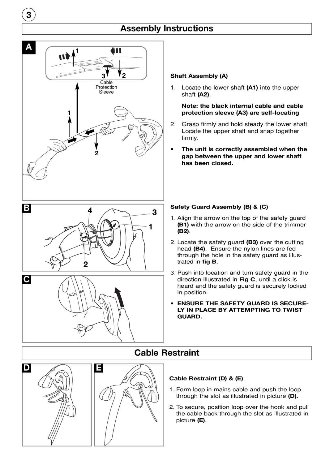
The Flymo Edger and Trimmer is an essential gardening tool designed to help homeowners achieve a neat and tidy garden effortlessly. This versatile device combines the functions of edging and trimming, making it easier for users to maintain a well-groomed lawn and sharp garden borders. With its user-friendly design, the Flymo Edger and Trimmer is perfect for both casual gardeners and enthusiasts alike.One of the standout features of the Flymo Edger and Trimmer is its lightweight design. Weighing significantly less than many traditional trimmers, it ensures that even less experienced users can maneuver it with ease. This lightweight construction does not compromise its robustness, as it is made with durable materials that are built to withstand the rigors of regular gardening tasks.
The Flymo Edger and Trimmer employs advanced technologies that enhance its performance. The powerful electric motor provides sufficient torque, enabling it to cut through grass and weeds effortlessly. Its sharp, durable blades ensure precise cuts, allowing users to achieve perfectly straight edges along flower beds, pathways, and driveways. The cutting width is adjustable, giving users the flexibility to select the best setting for their specific trimming needs.
Additionally, this tool often features an innovative dual-function system, allowing quick transitions between edging and trimming. Users can easily switch from vertical edging to horizontal trimming with minimal effort, making it an incredibly versatile addition to any gardening toolkit.
Another notable characteristic is the ergonomic handle, designed to provide maximum comfort during prolonged use. The handle's adjustable height ensures that users of all sizes can operate the trimmer comfortably, minimizing the risk of strain or fatigue. This ergonomic design, coupled with the lightweight nature of the tool, enables gardeners to work for extended periods without discomfort.
For added convenience, many models come with a spool and line system that simplifies the process of replacing trimming lines. This easy-adjust system minimizes downtime during gardening projects, allowing users to focus on the task at hand.
In summary, the Flymo Edger and Trimmer is a reliable, efficient, and user-friendly gardening tool that combines performance and convenience. With its lightweight design, powerful motor, dual-function capability, and ergonomic features, it provides a superior gardening experience for anyone looking to maintain a pristine outdoor space. Whether edging along flower beds or trimming overgrown grass, the Flymo Edger and Trimmer stands out as an invaluable tool in any garden maintenance arsenal.

