Configuring
Web-based Manager
Use the following procedure to connect to the
To connect to the web-based manager
1.Connect the management port of the FortiBridge unit to Ethernet port of the manage- ment computer.
Use a
2.Configure the management computer to be on the same subnet as the FortiBridge management port interface.
To do this, change the IP address of the management computer to 192.168.1.2 and the netmask to 255.255.255.0.
3.To access the FortiBridge
4.Type admin in the Name field and click Login.
To configure Probes
Probes monitor the FortiGate unit by sending packets from the INT 2 interface through the FortiGate unit to the EXT 2 interface. If probe packets are not received at the EXT 2 interface the FortiBridge unit detects a failure.
Configure probe settings to set actions on failure, add a dynamic IP pattern used by the
computer. Use these settings: Baud Rate 9600, Data bits 8, Parity None, Stop bits 1, Flow Control None.
3.At the login: prompt, type admin and press Enter twice.
(The login prompt is preceded by the server default host name.)
To configure the FortiBridge unit using the CLI
1. | Change the management IP address. |
| config system manageip |
| set ip <intf_ip>/<netmask_ip> |
| end |
2. | Configure the primary and secondary DNS server IP addresses. |
| config system dns |
| set primary |
| set secondary |
| end |
3. | Configure the default gateway. |
| config system route |
| edit 1 |
| set gateway <gateway_ip> |
| end |
4. | Change the administrator password. |
| config system admin |
QuickStart Guide
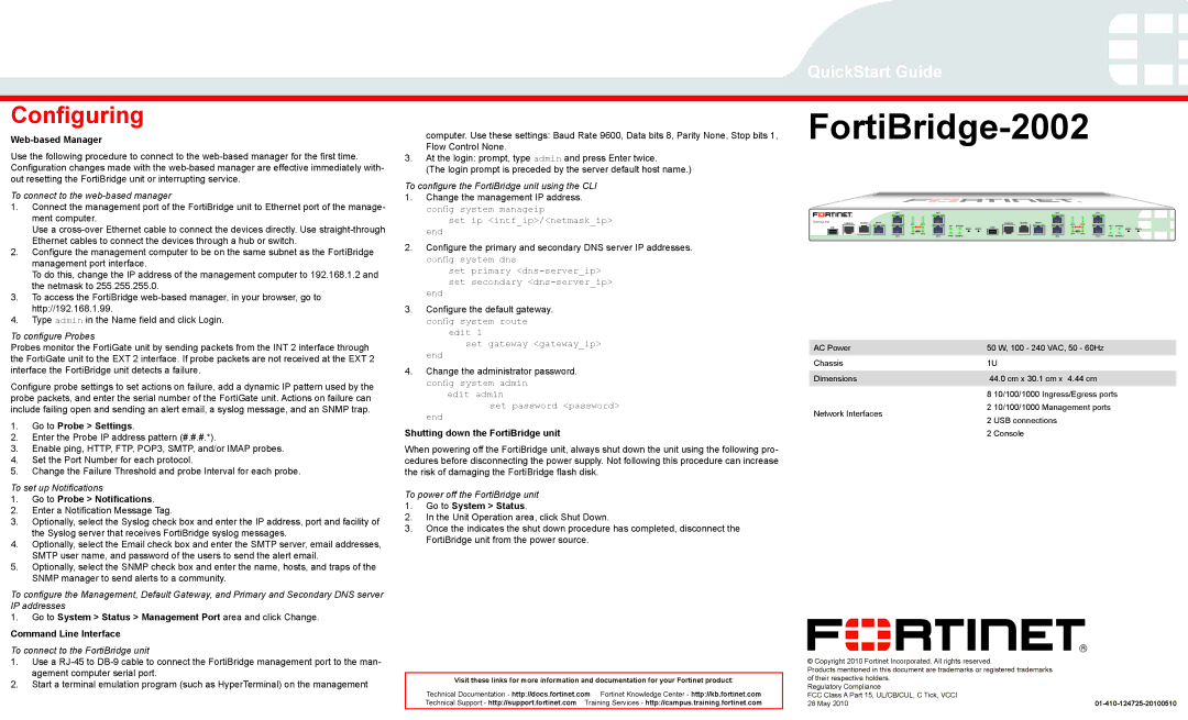
FortiBridge-2002
|
|
|
| INT1 | EXT1 |
|
|
|
|
|
| INT3 | EXT3 |
|
|
|
FortiBridge 2002 | CONSOLE1 | MODEM1 | MGMT1 | INT1 | EXT1 |
|
|
| CONSOLE2 | MODEM2 | MGMT2 | INT3 | EXT3 |
|
|
|
|
|
|
| HA1 | BYPASS1 |
|
|
|
| HA2 | BYPASS2 |
| ||||
| USB1 |
|
|
|
|
| USB2 |
|
|
|
|
| ||||
|
|
|
|
|
|
| MODE1 | RESET1 |
|
|
|
|
|
| MODE2 | RESET2 |
|
|
|
| INT2 | EXT2 | PWR1 | NORMAL1 |
|
|
|
| INT4 | EXT4 | PWR2 | NORMAL2 |
|
|
|
|
| INT2 | EXT2 |
|
|
|
| INT4 | EXT4 |
|
AC Power | 50 W, 100 - 240 VAC, 50 - 60Hz |
Chassis | 1U |
Dimensions | 44.0 cm x 30.1 cm x 4.44 cm |
probe packets, and enter the serial number of the FortiGate unit. Actions on failure can include failing open and sending an alert email, a syslog message, and an SNMP trap.
1.Go to Probe > Settings.
2.Enter the Probe IP address pattern (#.#.#.*).
3.Enable ping, HTTP, FTP, POP3, SMTP, and/or IMAP probes.
4.Set the Port Number for each protocol.
5.Change the Failure Threshold and probe Interval for each probe.
To set up Notifications
1.Go to Probe > Notifications.
2.Enter a Notification Message Tag.
3.Optionally, select the Syslog check box and enter the IP address, port and facility of the Syslog server that receives FortiBridge syslog messages.
4.Optionally, select the Email check box and enter the SMTP server, email addresses, SMTP user name, and password of the users to send the alert email.
5.Optionally, select the SNMP check box and enter the name, hosts, and traps of the SNMP manager to send alerts to a community.
To configure the Management, Default Gateway, and Primary and Secondary DNS server IP addresses
1.Go to System > Status > Management Port area and click Change.
Command Line Interface
To connect to the FortiBridge unit
edit admin |
set password <password> |
end |
Shutting down the FortiBridge unit
When powering off the FortiBridge unit, always shut down the unit using the following pro- cedures before disconnecting the power supply. Not following this procedure can increase the risk of damaging the FortiBridge flash disk.
To power off the FortiBridge unit
1.Go to System > Status.
2.In the Unit Operation area, click Shut Down.
3.Once the indicates the shut down procedure has completed, disconnect the FortiBridge unit from the power source.
Network Interfaces
8 10/100/1000 Ingress/Egress ports
2 10/100/1000 Management ports
2 USB connections
2 Console
1.Use a
2.Start a terminal emulation program (such as HyperTerminal) on the management
Visit these links for more information and documentation for your Fortinet product:
Technical Documentation - http://docs.fortinet.com Fortinet Knowledge Center - http://kb.fortinet.com Technical Support - http://support.fortinet.com Training Services - http://campus.training.fortinet.com
© Copyright 2010 Fortinet Incorporated. All rights reserved. |
|
Products mentioned in this document are trademarks or registered trademarks |
|
of their respective holders. |
|
Regulatory Compliance |
|
FCC Class A Part 15, UL/CB/CUL, C Tick, VCCI |
|
28 May 2010 |