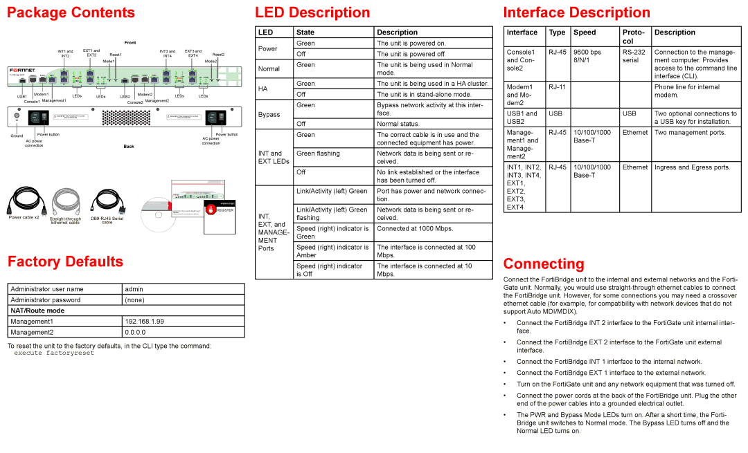
Package Contents
INT1 and | EXT1 and | Reset1 | INT3 and | EXT3 and | Reset2 | ||||
INT2 | EXT2 | INT4 | EXT4 | ||||||
|
|
|
| Mode1 |
|
|
|
| Mode2 |
|
|
|
|
|
|
|
|
|
|
|
|
|
|
|
|
|
|
|
|
|
|
|
| INT1 | EXT1 |
|
|
|
|
|
| INT3 | EXT3 |
|
|
|
FortiBridge 2002 | CONSOLE1 | MODEM1 | MGMT1 | INT1 | EXT1 |
|
|
| CONSOLE2 | MODEM2 | MGMT2 | INT3 | EXT3 |
|
|
|
USB1 |
|
|
|
|
| HA1 | BYPASS1 |
| USB2 |
|
|
|
| HA2 | BYPASS2 |
|
|
|
|
|
|
| MODE1 | RESET1 |
|
|
|
|
| MODE2 | RESET2 | ||
|
|
|
| INT2 | EXT2 | PWR1 | NORMAL1 |
|
|
|
| INT4 | EXT4 | PWR2 | NORMAL2 |
|
|
|
|
| INT2 | EXT2 |
|
|
|
| INT4 | EXT4 |
|
|
|
|
|
|
|
|
| Modem1 |
|
|
|
|
|
|
|
|
|
|
| Modem2 |
|
|
|
|
|
|
|
|
|
|
|
|
| ||||||||
|
|
|
|
|
|
|
|
|
|
|
|
|
|
|
|
|
|
|
|
|
|
|
|
|
|
|
|
|
|
|
| ||||||||||
| USB1 |
|
| LEDs |
| LEDs | USB2 | LEDs | LEDs | ||||||||||||||||||||||||||||||||
|
|
|
|
| Console1 Management1 |
|
|
|
|
| Console2 | Management2 |
|
|
|
|
|
|
|
|
|
|
|
|
| ||||||||||||||||
|
|
|
|
|
|
|
|
|
|
|
|
|
|
|
|
|
|
|
|
|
|
|
|
|
|
|
|
|
|
|
|
|
|
|
|
|
|
|
|
|
|
|
|
|
|
|
|
|
|
|
|
|
|
| DISCONNECT TWO POWER SUPPLY CORDS |
|
|
|
|
|
|
|
|
|
|
| DISCONNECT TWO POWER SUPPLY CORDS |
|
|
|
|
|
|
|
|
| |||||||
|
|
|
|
|
|
|
|
|
|
|
|
| BEFORE SERVICING |
|
|
|
|
|
|
|
|
|
|
|
| BEFORE SERVICING |
|
|
|
|
|
|
|
|
| ||||||
|
|
|
|
|
|
|
|
|
|
|
|
|
|
|
|
|
|
|
|
|
|
|
|
|
|
|
|
|
|
|
|
|
|
|
|
|
|
|
|
|
|
|
|
|
|
|
|
|
|
|
|
|
|
|
|
|
|
|
|
|
|
|
|
|
|
|
|
|
|
|
|
|
|
|
|
|
|
|
|
|
|
| |
|
|
|
|
|
|
|
|
|
|
|
|
|
|
|
|
|
|
|
|
|
|
|
|
|
|
|
|
|
|
|
|
|
|
| |||||||
Ground |
|
|
|
|
| Power button |
|
|
|
|
|
|
|
|
|
|
|
|
|
|
| AC |
| Power button | |||||||||||||||||
|
|
|
|
|
|
|
|
|
|
|
|
|
|
|
|
|
|
|
|
|
|
|
|
|
|
|
|
|
|
|
|
| power | ||||||||
|
|
|
|
| AC power |
|
|
|
|
|
|
|
|
|
|
|
|
|
|
|
|
|
|
|
| ||||||||||||||||
|
|
|
|
|
|
|
|
|
|
|
|
|
|
|
|
|
|
|
|
|
|
|
|
| connection | ||||||||||||||||
|
|
|
|
| connection |
|
|
|
|
|
|
|
|
|
|
|
|
|
|
|
|
|
|
|
| ||||||||||||||||
|
|
|
|
|
|
|
|
|
|
|
|
|
|
|
|
|
|
|
|
|
|
|
|
|
|
|
|
|
|
|
|
|
| ||||||||
LED Description
LED | State | Description | |
Power | Green | The unit is powered on. | |
Off | The unit is powered off. | ||
| |||
Normal | Green | The unit is being used in Normal | |
| mode. | ||
|
| ||
HA | Green | The unit is being used in a HA cluster. | |
Off | The unit is in | ||
| |||
| Green | Bypass network activity at this inter- | |
Bypass |
| face. | |
| Off | Normal status. | |
| Green | The correct cable is in use and the | |
|
| connected equipment has power. | |
INT and | Green flashing | Network data is being sent or re- | |
EXT LEDs |
| ceived. | |
| Off | No link established or the interface | |
|
| has been turned off. |
Interface Description
Interface | Type | Speed | Proto- | Description |
|
|
| col |
|
Console1 | 9600 bps | Connection to the manage- | ||
and Con- |
| 8/N/1 | serial | ment computer. Provides |
sole2 |
|
|
| access to the command line |
|
|
|
| interface (CLI). |
Modem1 |
|
| Phone line for internal | |
and Mo- |
|
|
| modem. |
dem2 |
|
|
|
|
USB1 and | USB |
| USB | Two optional connections to |
USB2 |
|
|
| a USB key for installation. |
Manage- | 10/100/1000 | Ethernet | Two management ports. | |
ment1 and |
|
|
| |
Manage- |
|
|
|
|
ment2 |
|
|
|
|
INT1, INT2, | 10/100/1000 | Ethernet | Ingress and Egress ports. | |
INT3, INT4, |
|
|
|
Power cable x2
Ethernet cable | cable |
QuickStart Guide
Tools and Documenation
Copyright 2010 Fortinet Incorporated. All rights reserved. | REGISTER |
Trademarks |
|
Products mentioned in this document are trademarks. |
|
| Link/Activity (left) Green | Port has power and network connec- | |
|
| tion. | |
INT, | Link/Activity (left) Green | Network data is being sent or re- | |
flashing | ceived. | ||
EXT, and |
|
| |
Speed (right) indicator is | Connected at 1000 Mbps. | ||
MANAGE- | |||
Green |
| ||
MENT |
|
| |
Speed (right) indicator is | The interface is connected at 100 | ||
Ports |
EXT1, |
EXT2, |
EXT3, |
EXT4 |
Factory Defaults
Administrator user name | admin |
Administrator password | (none) |
NAT/Route mode |
|
Management1 | 192.168.1.99 |
Management2 | 0.0.0.0 |
To reset the unit to the factory defaults, in the CLI type the command: execute factoryreset
Amber | Mbps. |
Speed (right) indicator | The interface is connected at 10 |
is Off | Mbps. |
Connecting
Connect the FortiBridge unit to the internal and external networks and the Forti- Gate unit. Normally, you would use
•Connect the FortiBridge INT 2 interface to the FortiGate unit internal inter- face.
•Connect the FortiBridge EXT 2 interface to the FortiGate unit external interface.
•Connect the FortiBridge INT 1 interface to the internal network.
•Connect the FortiBridge EXT 1 interface to the external network.
•Turn on the FortiGate unit and any network equipment that was turned off.
•Connect the power cords at the back of the FortiBridge unit. Plug the other end of the power cables into a grounded electrical outlet.
•The PWR and Bypass Mode LEDs turn on. After a short time, the Forti- Bridge unit switches to Normal mode. The Bypass LED turns off and the Normal LED turns on.