LED | State | Description | |
Power | Green | The FortiGate unit is on. | |
|
| ||
Off | The FortiGate unit is off. | ||
| |||
|
|
| |
| Green | The correct cable is in use and the connected equip- | |
Display Panel LEDs: |
| ment has power. | |
1, 2, 3, 4 | Flashing | Network activity at this interface. | |
5/HA, INT, EXT | Green |
| |
| Off | No link established. | |
|
|
| |
| Amber | The link is up. | |
| Flashing | Network activity at this interface. | |
Port 1 | Amber |
| |
| Green | Link speed is 100Mb/s | |
| Off | Link speed is 10Mb/s | |
| Amber | The link is up. | |
|
|
| |
| Flashing | Network activity at this interface. | |
Internal, External | Amber |
| |
| Green | Link speed is 1000Mb/s | |
| Off | Link speed is 100Mb/s |
|
|
|
|
|
|
|
|
|
|
|
|
|
|
|
| POWER | 1 | 2 | 3 |
| ||
Esc | Enter |
|
|
|
|
|
|
|
|
|
|
|
|
|
|
|
|
|
|
| ||
|
|
|
|
|
|
|
|
|
|
|
|
|
|
|
| 4 | 5/HA | INT | EXT | |||
| 1 |
| 2 |
| 3 |
| 4 |
|
| 5/HA |
|
| INTERNAL |
| EXTERNAL |
| ||||||
|
|
|
|
|
|
|
|
|
|
|
|
|
|
|
|
|
|
|
|
|
|
|
|
|
|
|
|
|
|
|
|
|
|
|
|
|
|
|
|
|
|
|
|
|
|
|
|
|
|
|
|
|
|
|
|
|
|
|
|
|
|
|
|
|
|
|
|
|
© Copyright 2009 Fortinet Incorporated. All rights reserved.
Products mentioned in this document are trademarks or registered trade- marks of their respective holders.
Regulatory Compliance
FCC Class A Part 15 CSA/CUS01-30006-0041-20090123
23 January 2009
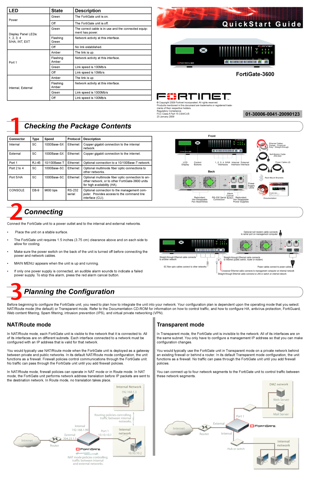
Checking the Package Contents
Connector | Type | Speed | Protocol | Description |
Internal | SC | Ethernet | Copper gigabit connection to the internal | |
|
|
|
| network. |
External | SC | Ethernet | Copper gigabit connection to the internet. | |
|
|
|
|
|
Port 1 | Ethernet | Optional connection to a | ||
|
|
|
|
|
Port 2 to 4 | SC | Ethernet | Optional multimode fiber optic connections to | |
|
|
|
| other networks. |
Port 5/HA | SC | Ethernet | Optional multimode fiber optic connection to an- | |
|
|
|
| other network, or to other |
|
|
|
| for high availability (HA). |
CONSOLE | 9600 bps | Optional connection to the management com- | ||
|
|
| serial | puter. Provides access to the command line |
|
|
|
| interface (CLI). |
 Connecting
Connect the FortiGate unit to a power outlet and to the internal and external networks.
Front
|
|
|
|
|
|
|
|
|
|
|
|
|
| POWER | 1 | 2 | 3 |
| ||
Esc | Enter |
|
|
|
|
|
|
|
|
|
|
|
|
|
|
|
|
| ||
|
|
|
|
|
|
|
|
|
|
|
|
|
| 4 | 5/HA | INT | EXT | |||
| 1 |
| 2 |
| 3 |
| 4 |
| 5/HA |
|
| INTERNAL |
| EXTERNAL |
| |||||
|
|
|
|
|
|
|
|
|
|
|
|
|
|
|
|
|
|
|
|
|
|
|
|
|
|
|
|
|
|
|
|
|
|
|
|
|
|
|
|
|
|
|
|
|
|
|
|
|
|
|
|
| |
LCD | Control | 1, 2, 3, |
| 4, 5/HA |
|
|
|
| |||
Internal | External | ||||||||||
| |||||||||||
Display | Buttons | Interfaces | Interface Interface | ||||||||
Back
|
|
|
|
|
|
|
|
|
|
|
|
|
|
|
|
|
| Power |
|
|
|
|
|
|
|
|
|
|
|
|
|
|
|
|
|
| |
|
|
|
|
|
|
|
|
|
|
|
|
|
|
|
|
|
| Supply |
|
|
|
|
|
|
|
|
|
|
|
|
|
|
|
|
|
| LEDs |
|
|
|
|
|
|
|
|
|
|
|
|
|
|
|
|
|
| |
|
|
|
|
|
|
|
|
|
|
|
|
|
|
|
|
| ||
|
|
|
|
|
|
|
| Alarm |
|
|
|
|
|
|
| |||
|
|
|
|
|
|
|
| Cancel |
|
|
|
|
|
|
| |||
| Redundant | Redundant | ||||||||||||||||
Connection |
|
|
|
| Hot Swappable | |||||||||||||
Fan Assemblies |
|
|
|
|
|
|
| Power Supplies | ||||||||||
Ethernet Cables:
Orange - Crossover
Grey -
Power Cables (2)
Q u i c k S t a r t G u i d e
Copyright 2006 Fortinet Incorporated. All rights reserved.
Trademarks
Products mentioned in this document are trademarks.
Documentation
•Place the unit on a stable surface.
•The FortiGate unit requires 1.5 inches (3.75 cm) clearance above and on each side to allow for cooling.
•Make sure the power switch on the back of the unit is turned off before connecting the power and network cables.
•MAIN MENU appears when the unit is up and running.
•If only one power supply is connected, an audible alarm sounds to indicate a failed power supply. To stop this alarm, press the red alarm cancel button.
|
|
|
|
|
|
|
|
|
| Optional null modem cable connects |
|
|
|
|
|
|
|
|
|
| to serial port on management computer |
|
|
|
|
|
| POWER | 1 | 2 | 3 |
|
Esc | Enter |
|
|
|
|
|
|
|
|
|
|
|
|
|
|
| 4 | 5/HA | INT | EXT | |
| 1 | 2 | 3 | 4 | 5/HA | INTERNAL |
| EXTERNAL |
| |
| ||
to another network | or | to Internet (public switch, router or modem) |
SC fiber optic cables connect to other networks |
| Power cables connect to power outlets |
Crossover Ethernet cable connects to management computer on internal network
 Planning the Configuration
Before beginning to configure the FortiGate unit, you need to plan how to integrate the unit into your network. Your configuration plan is dependent upon the operating mode that you select: NAT/Route mode (the default) or Transparent mode. Refer to the Documentation
NAT/Route mode
In NAT/Route mode, each FortiGate unit is visible to the network that it is connected to. All of its interfaces are on different subnets. Each interface connected to a network must be configured with an IP address that is valid for that network.
You would typically use NAT/Route mode when the FortiGate unit is deployed as a gateway between private and public networks. In its default NAT/Route mode configuration, the unit functions as a firewall. Firewall policies control communications through the FortiGate unit. No traffic can pass through the FortiGate unit until you add firewall policies.
In NAT/Route mode, firewall policies can operate in NAT mode or in Route mode. In NAT mode, the FortiGate unit performs network address translation before IP packets are sent to the destination network. In Route mode, no translation takes place.
Internal Network
192.168.1.3
Routing policies controlling traffic between internal networks.
Internal |
|
| |
192.168.1.99 | Port 1 | Internal | |
| network | ||
External | 10.10.10.1 | ||
|
Internet | 204.23.1.5 |
| |
| Router |
10.10.10.2
NAT mode policies controlling traffic between internal and external networks.
Transparent mode
In Transparent mode, the FortiGate unit is invisible to the network. All of its interfaces are on the same subnet. You only have to configure a management IP address so that you can make configuration changes.
You would typically use the FortiGate unit in Transparent mode on a private network behind an existing firewall or behind a router. In its default Transparent mode configuration, the unit functions as a firewall. No traffic can pass through the FortiGate unit until you add firewall policies.
You can connect up to four network segments to the FortiGate unit to control traffic between these network segments.
DMZ network
| Web Server |
Port 1 | Mail Server |
|
External
Internet
Router Internal
Internal network
Hub or switch