FortiMail Unit LED Indicators
LED | State | Description | |
Power | On | The FortiMail unit is on. | |
Off | The FortiMail unit is off. | ||
| |||
Port 1 to 6 | Amber | Port has power and network | |
Left LED |
| connection. | |
Flashing Amber | Network activity at this interface. | ||
| |||
Port 1 to 6 | Off | Port connected at 10 Mbps. | |
Right LED |
|
| |
Green | Port connected at up to 100 Mbps. | ||
| Red (Port 5 and 6) | Port connected at 1000 Mbps. |
For more information
•Documentation CD: all major Fortinet product documentation
•Fortinet Technical Documentation: http://docs.fortinet.com
•Fortinet Knowledge Center: http://kc.fortinet.com
•Fortinet Technical Support: http://support.fortinet.com
QuickStart Guide
Esc | Enter | CONSOLE | USB |
|
| 10/100 |
|
| 10/100/1000 |
|
| 1 | 2 | 3 | 4 | 5 | 6 |
© Copyright 2009 Fortinet Incorporated. All rights reserved.
Trademarks
Products mentioned in this document are trademarks or registered trademarks of their respective holders.
Regulatory Compliance
FCC Class A Part 15, CE, and UL
June 19, 2009
http://www.fortinet.com
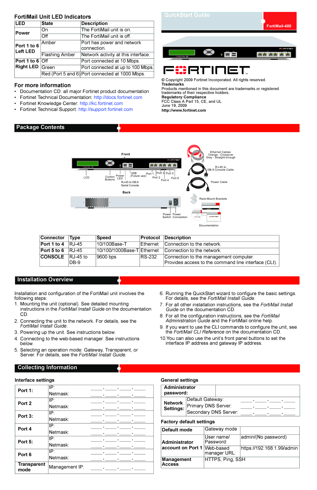
Package Contents
Front | Ethernet Cables: |
Orange - Crossover | |
- | Grey - |
| Esc | Enter | CONSOLE | USB |
|
| 10/100 |
|
| 10/100/1000 |
|
|
| 1 | 2 | 3 | 4 | 5 | 6 | ||
|
|
|
|
|
|
|
|
|
| |
|
|
|
| USB |
|
| Port 3 |
| ||
|
|
| Power | Port 1 | Port 5 | |||||
LCD | Control | (Future use) | Port 2 |
|
| Port 6 | ||||
| Buttons | LED |
|
|
|
| Port 4 | |||
|
|
|
|
|
|
|
| Power Cable | ||
|
|
| Serial Console |
|
|
|
|
|
| |
|
|
| Back |
|
|
|
|
|
| |
|
|
|
|
|
|
|
|
|
| |
Power Power Switch Connection
QuickStartGuide Guide
ools and Documenation
Copyright 2008 Fortinet
Trademarks
Welcome Bienvenue Willkommen | Bienvenido Benvenuto |
|
|
|
| Documentation |
|
|
|
|
|
Connector | Type | Speed | Protocol | Description |
Port 1 to 4 | Ethernet | Connection to the network. | ||
Port 5 to 6 | Ethernet | Connection to the network. | ||
CONSOLE | 9600 bps | Connection to the management computer. | ||
|
|
| Provides access to the command line interface (CLI). |
Installation Overview
Installation and configuration of the FortiMail unit involves the following steps:
1.Mounting the unit (optional). See detailed mounting instructions in the FortiMail Install Guide on the documentation CD.
2.Connecting the unit to the network. For details, see the FortiMail Install Guide.
3.Powering up the unit. See instructions below.
4.Connecting to the
5.Selecting an operation mode: Gateway, Transparent, or Server. For details, see the FortiMail Install Guide.
6.Running the QuickStart wizard to configure the basic settings. For details, see the FortiMail Install Guide.
7.For all other installation instructions, see the FortiMail Install Guide on the documentation CD.
8.For all the configuration instructions, see the FortiMail Administration Guide and the FortiMail online help.
9.If you want to use the CLI commands to configure the unit, see the FortiMail CLI Reference on the documentation CD.
10.You can also use the unit’s front panel buttons to set the interface IP address and gateway IP address.
Collecting Information
Interface settings |
| ||
|
|
| |
Port 1: | IP: | ____.____.____.____ | |
Netmask: | ____.____.____.____ | ||
| |||
Port 2 | IP: | ____.____.____.____ | |
Netmask: | ____.____.____.____ | ||
| |||
Port 3: | IP: | ____.____.____.____ | |
Netmask: | ____.____.____.____ | ||
| |||
Port 4 | IP: | ____.____.____.____ | |
Netmask: | ____.____.____.____ | ||
| |||
Port 5: | IP: | ____.____.____.____ | |
Netmask: | ____.____.____.____ | ||
| |||
Port 6 | IP: | ____.____.____.____ | |
Netmask: | ____.____.____.____ | ||
| |||
Transparent | Management IP: | ____.____.____.____ | |
mode | |||
General settings |
|
|
| |
|
|
|
| |
Administrator |
|
|
| |
password: |
|
|
| |
Network | Default Gateway: | ____.____.____.____ | ||
Settings: | Primary DNS Server: | ____.____.____.____ | ||
| Secondary DNS Server: ____.____.____.____ | |||
Factory default settings |
| |||
|
|
| ||
Default mode | Gateway mode |
| ||
|
|
|
| |
Administrator | User name/ | admin/(No password) | ||
Password: |
| |||
account on Port 1 |
|
| ||
https://192.168.1.99/admin | ||||
|
| manager URL: |
| |
Management | HTTPS, Ping, SSH | |||
Access |
|
|
|
|