Model PH-100
Rear Panel section
1 | 2 | 3 | 4 | 5 | 6 | 7 | ||
|
|
|
|
|
|
|
| |
|
|
|
|
|
|
|
|
|
AC IN
5 | 4 | 3 | 2 | 1 | L |
10 | 9 | 8 | 7 | 6 | R |
| |||||
PHONES (PRIORITY TO "FRONT PHONES" OUTPUT) |
| CASCADE | |||
| OUT | ||||
5 | 4 | 3 | 2 | 1 | L/MONO |
10 | 9 | 8 | 7 | 6 | R |
|
| CHANNEL IN |
| AUX IN | |
|
|
| |||
L/MONO
R
INPUT
+4dBu
INPUT L
|
| XLR | PHONE |
+4dBu | HOT | 2 | T |
COLD | 3 | R | |
| GND | 1 | S |
INPUT R
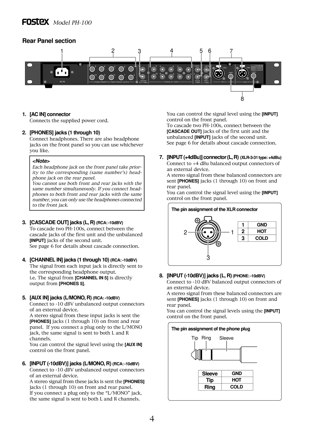
1. [AC IN] connector
Connects the supplied power cord.
2. [PHONES] jacks (1 through 10)
Connect headphones. There are also headphone jacks on the front panel so you can use whichever you like.
8
You can control the signal level using the [INPUT] control on the front panel.
To cascade two
See page 6 for details about cascade connection.
<Note>
Each headphone jack on the front panel take prior- ity to the corresponding (same number's) head- phone jack on the rear panel.
You cannot use both front and rear jacks with the same number simultaneously. If you connect head- phones to both front and rear jacks with the same number, you can only use the headphones connected to the front jack.
3. [CASCADE OUT] jacks (L, R) (RCA: -10dBV)
To cascade two
See page 6 for details about cascade connection.
4. [CHANNEL IN] jacks (1 through 10) (RCA: -10dBV)
The signal from each input jack is directly sent to the corresponding headphone output.
i.e. The signal from [CHANNEL IN 5] is directly output from [PHONES 5].
5. [AUX IN] jacks (L/MONO, R) (RCA: -10dBV)
Connect to
A stereo signal from these input jacks is sent the [PHONES] jacks (1 through 10) on front and rear panel. If you connect a plug only to the L/MONO jack, the same signal is sent to both L and R channels.
You can control the signal level using the [AUX IN] control on the front panel.
6. [INPUT (-10dBV)] jacks (L/MONO, R) (RCA: -10dBV)
Connect to
A stereo signal from these jacks is sent the [PHONES] jacks (1 through 10) on front and rear panel.
If you connect a plug only to the “L/MONO” jack, the same signal is sent to both L and R channels.
7. [INPUT (+4dBu)] connector (L, R) (XLR-3-31 type: +4dBu)
Connect to +4 dBu balanced output connectors of an external device.
A stereo signal from these balanced connectors are sent [PHONES] jacks (1 through 10) on front and rear panel.
You can control the signal level using the [INPUT] control on the front panel.
The pin assignment of the XLR connector
| 1 | GND |
2 | 1 2 | HOT |
| 3 | COLD |
3
8. [INPUT (-10dBV)] jacks (L, R) (PHONE: -10dBV)
Connect to
A stereo signal from these balanced connectors are sent [PHONES] jacks (1 through 10) on front and rear panel.
You can control the signal levels using the [INPUT] control on the front panel.
The pin assignment of the phone plug
Tip Ring Sleeve
Sleeve | GND |
Tip | HOT |
Ring | COLD |
4
