LED Driver Design Procedures
Vin = 12V
Boost
Converter
(MC34063)
Vout = 30V
8 LEDs | 8 LEDs | 8 LEDs |
VLED x 8
PWM
Driver R
PWM
Driver G
Driver B | VREF |
ILED = 50mA
VDROP
PWM
Rs
VRS
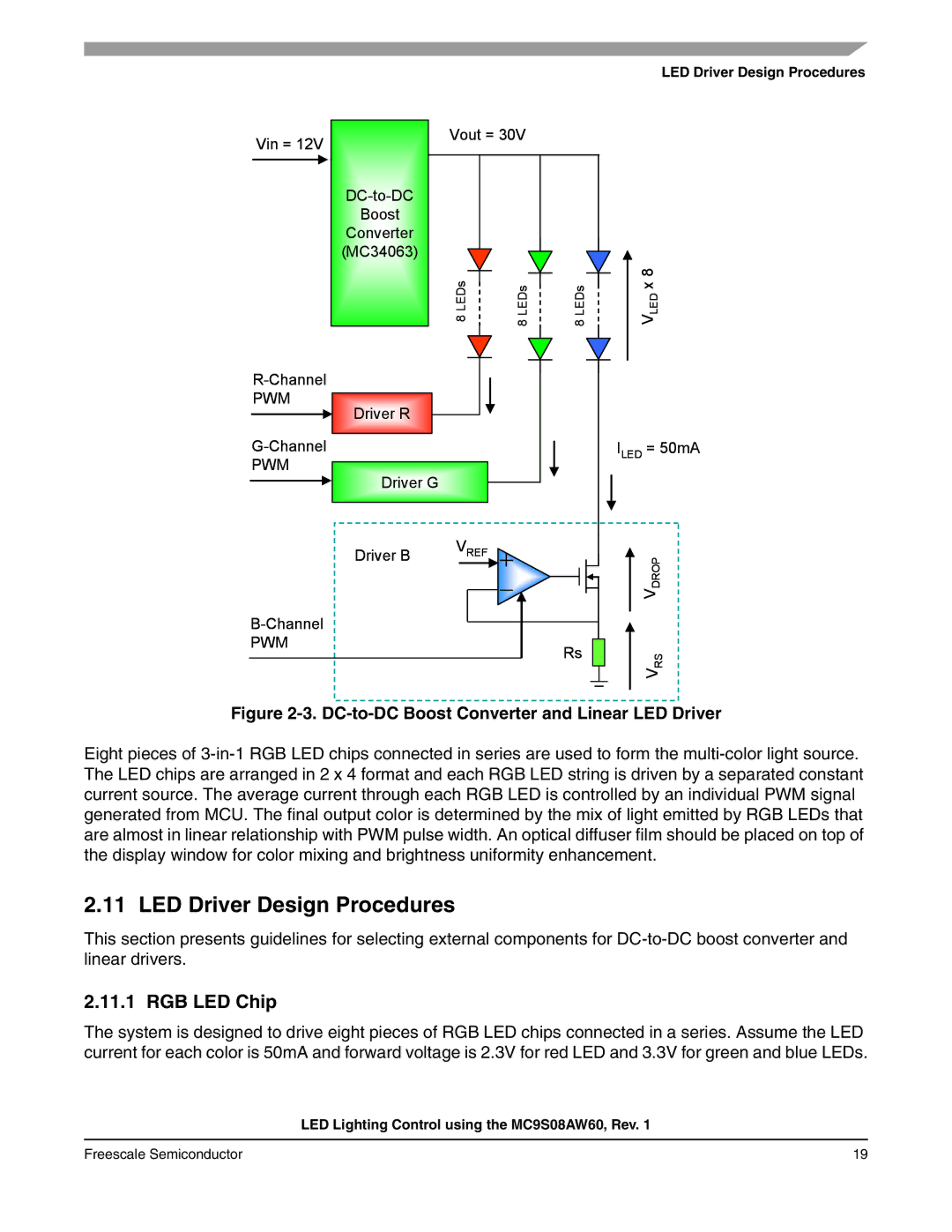
Figure 2-3. DC-to-DC Boost Converter and Linear LED Driver
Eight pieces of
2.11 LED Driver Design Procedures
This section presents guidelines for selecting external components for
2.11.1 RGB LED Chip
The system is designed to drive eight pieces of RGB LED chips connected in a series. Assume the LED current for each color is 50mA and forward voltage is 2.3V for red LED and 3.3V for green and blue LEDs.
LED Lighting Control using the MC9S08AW60, Rev. 1
Freescale Semiconductor | 19 |