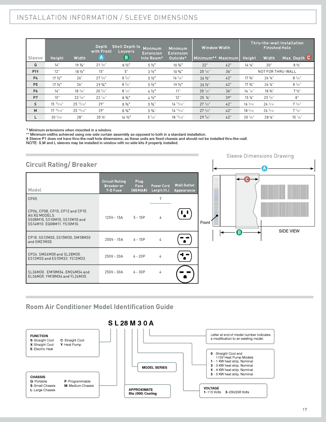
CP08, CP24, CP18, CP15, CP06 specifications
Friedrich CP08 is a highly regarded portable air conditioning unit designed to provide comfort in a multitude of environments. It is especially popular for applications in homes, offices, and small commercial spaces where traditional air conditioning may not be feasible. The CP08 integrates advanced cooling technologies and user-friendly features to enhance the air conditioning experience.One of the primary distinctions of the CP08 is its powerful cooling capability. With a cooling capacity of 8,000 BTUs, it can efficiently cool spaces up to approximately 350 square feet, making it ideal for medium-sized rooms. The unit also operates with a reasonable Energy Efficiency Ratio (EER), ensuring that it provides effective cooling without excessive energy consumption.
The CP08 features three cooling modes and three fan speeds, allowing users to adjust the unit according to their ambient conditions and personal preferences. This level of customization ensures that users can maintain a comfortable environment regardless of the outside temperature. Additionally, the unit is equipped with a programmable timer, allowing users to set specific run times, which is convenient for energy savings and automatic operation.
In terms of ease of use, the Friedrich CP08 includes a user-friendly remote control, enabling users to adjust settings from a distance. The integrated LED display shows current settings, while the easy-to-read control panel allows for straightforward operation. The unit's design also includes a washable and reusable air filter, promoting healthy air quality by capturing dust and allergens, and extending the life of the unit.
Another notable feature of the CP08 is its relatively lightweight and portable design, complete with wheels that allow for easy movement between rooms. This makes it an excellent choice for renters or those looking for a flexible cooling solution. The unit also has a quiet operation mode, ensuring that it runs quietly during use, which is particularly beneficial for nighttime cooling or in work settings.
The Friedrich CP08 stands out with its robust build quality, combining durability with efficient performance. This small yet powerful air conditioning unit proves that effective cooling solutions can be both versatile and comfortable, meeting the diverse needs of today’s consumers. Whether used in a bedroom, living room, or workspace, the Friedrich CP08 is designed to deliver reliable performance, making it a worthy investment for anyone seeking portable cooling solutions.

