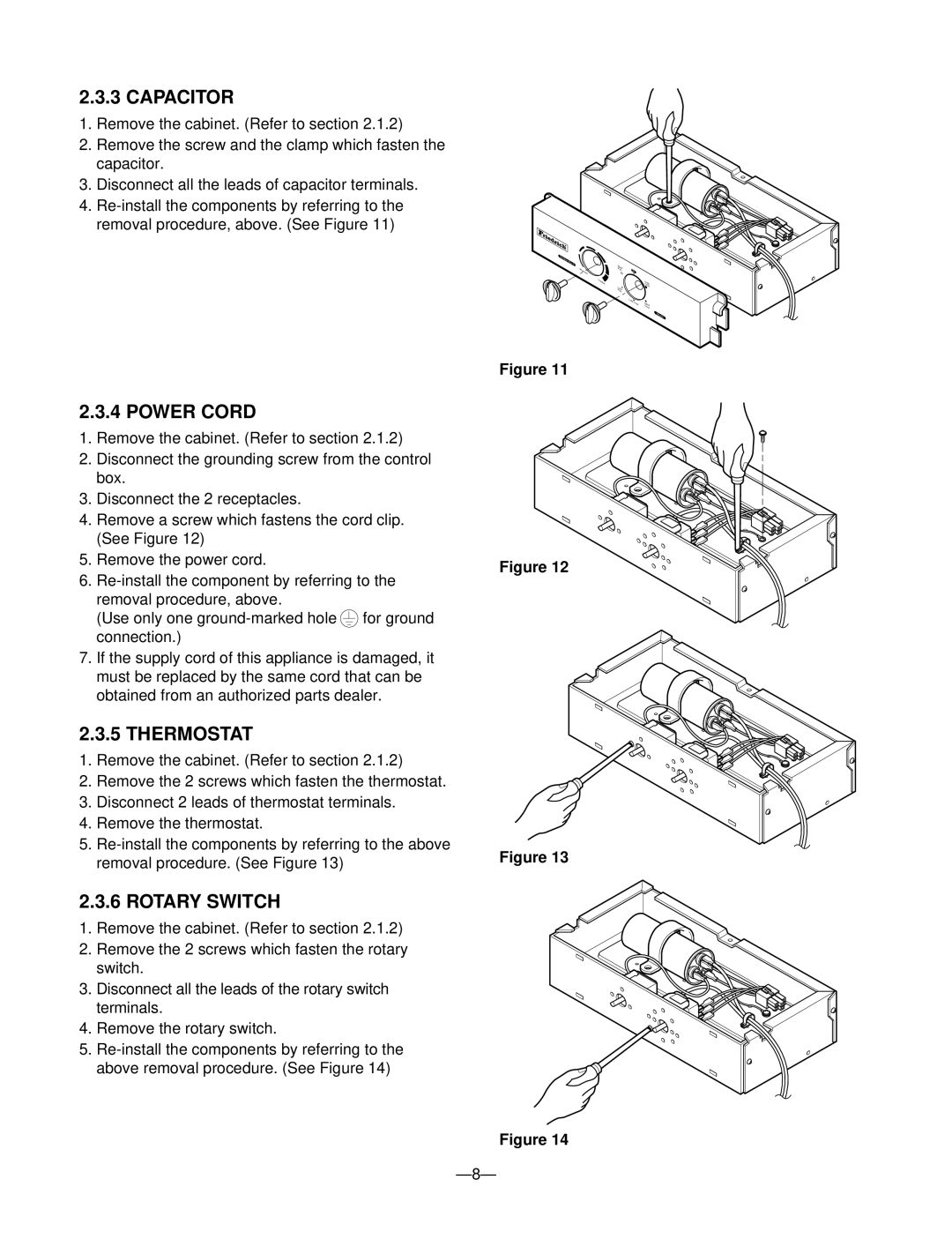
2.3.3 CAPACITOR
1.Remove the cabinet. (Refer to section 2.1.2)
2.Remove the screw and the clamp which fasten the capacitor.
3.Disconnect all the leads of capacitor terminals.
4.
2.3.4 POWER CORD
1.Remove the cabinet. (Refer to section 2.1.2)
2.Disconnect the grounding screw from the control box.
3.Disconnect the 2 receptacles.
4.Remove a screw which fastens the cord clip. (See Figure 12)
5.Remove the power cord.
6.
(Use only one | for ground |
connection.) |
|
7.If the supply cord of this appliance is damaged, it must be replaced by the same cord that can be obtained from an authorized parts dealer.
2.3.5 THERMOSTAT
1.Remove the cabinet. (Refer to section 2.1.2)
2.Remove the 2 screws which fasten the thermostat.
3.Disconnect 2 leads of thermostat terminals.
4.Remove the thermostat.
5.
Tem |
|
|
|
|
perat |
|
|
|
|
ure | Med |
|
|
|
Warmer |
|
|
| |
Fan | Off |
| ||
Cooler |
|
|
| High |
| Low |
|
| Cool |
| Fan |
|
|
|
|
| Low | Cool | Med |
|
|
| ||
|
|
|
| Cool |
Mode
Figure 11
Figure 12
Figure 13
2.3.6 ROTARY SWITCH
1. Remove the cabinet. (Refer to section 2.1.2)
2. Remove the 2 screws which fasten the rotary switch.
3. Disconnect all the leads of the rotary switch terminals.
4. Remove the rotary switch.
5.
Figure 14
— 8—