2.4 REFRIGERATION CYCLE
CAUTION
Discharge the refrigerant system using a FreonTM Recovery System.
Install a valve for the recovery before venting the Freon. Remove the valve when finished.
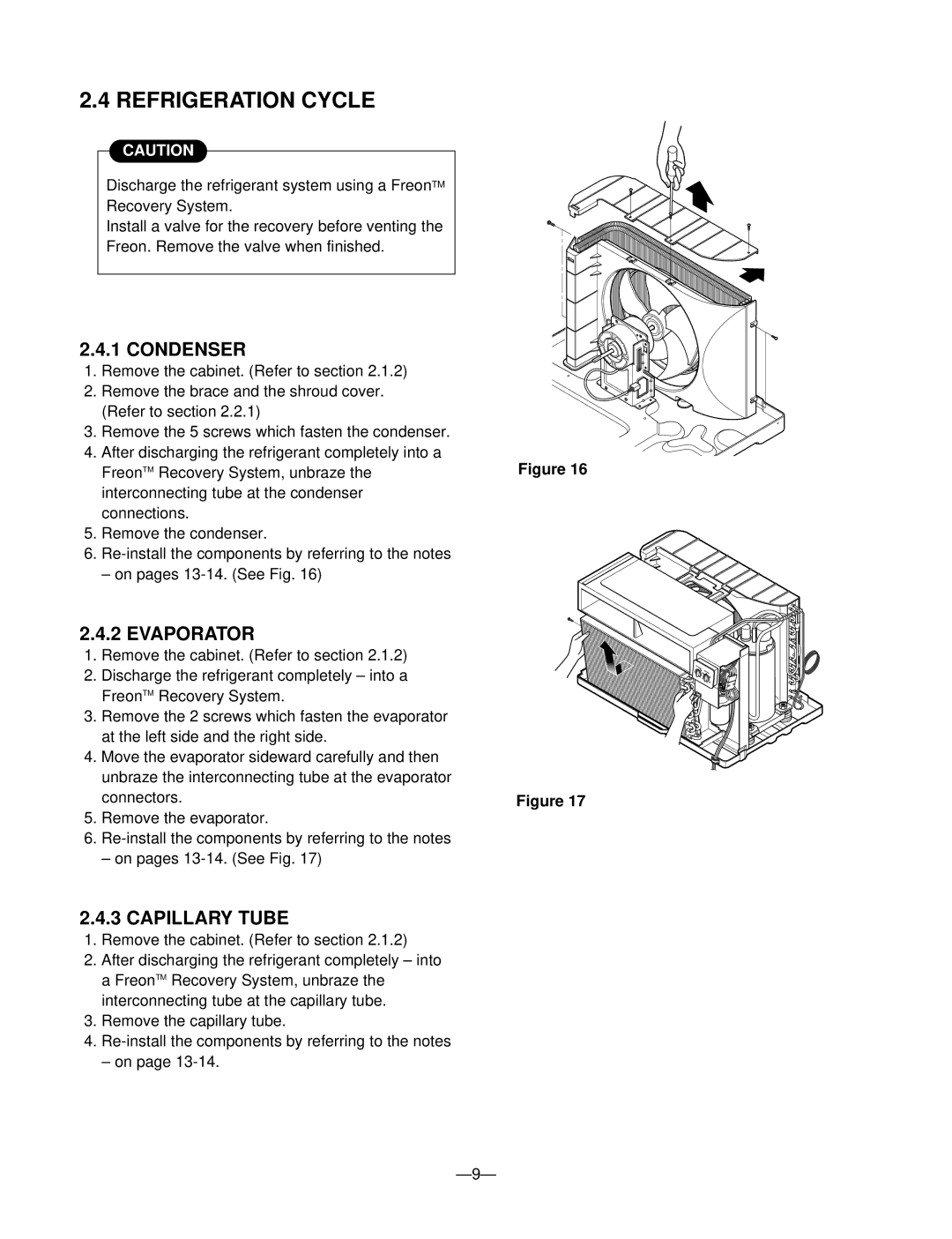
2.4.1 CONDENSER
1.Remove the cabinet. (Refer to section 2.1.2)
2.Remove the brace and the shroud cover. (Refer to section 2.2.1)
3.Remove the 5 screws which fasten the condenser.
4.After discharging the refrigerant completely into a FreonTM Recovery System, unbraze the interconnecting tube at the condenser connections.
5.Remove the condenser.
6.
– on pages
2.4.2 EVAPORATOR
1.Remove the cabinet. (Refer to section 2.1.2)
2.Discharge the refrigerant completely – into a FreonTM Recovery System.
3.Remove the 2 screws which fasten the evaporator at the left side and the right side.
4.Move the evaporator sideward carefully and then unbraze the interconnecting tube at the evaporator connectors.
5.Remove the evaporator.
6.
– on pages
2.4.3 CAPILLARY TUBE
1.Remove the cabinet. (Refer to section 2.1.2)
2.After discharging the refrigerant completely – into a FreonTM Recovery System, unbraze the interconnecting tube at the capillary tube.
3.Remove the capillary tube.
4.
– on page
Figure 16
Figure 17