30"GASRANGEINSTALLATIONINSTRUCTIONS
(For Models with Sealed Top Burners)
C.Level and Position Range - Level range by adjusting the
(4) leveling legs with a wrench. Note: A minimum clearance of 1/8" is required between the bottom of the range and the leveling leg to allow room for the bracket. Use a spirit level to check your adjustments. Slide range back into position. Visually check that rear leveling leg is inserted into and fully secured by the
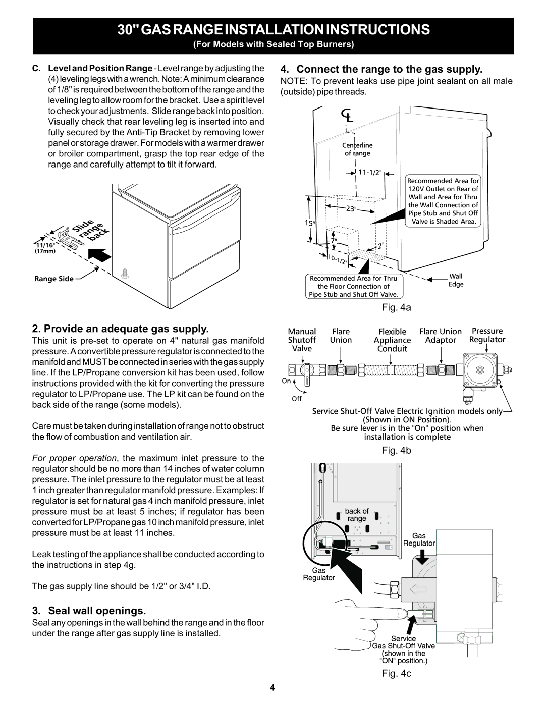
4. Connect the range to the gas supply.
NOTE: To prevent leaks use pipe joint sealant on all male (outside) pipe threads.
Fig. 4a
2. Provide an adequate gas supply.
This unit is
Care must be taken during installation of range not to obstruct the flow of combustion and ventilation air.
Fig. 4b
For proper operation, the maximum inlet pressure to the regulator should be no more than 14 inches of water column pressure. The inlet pressure to the regulator must be at least 1 inch greater than regulator manifold pressure. Examples: If regulator is set for natural gas 4 inch manifold pressure, inlet pressure must be at least 5 inches; if regulator has been converted for LP/Propane gas 10 inch manifold pressure, inlet pressure must be at least 11 inches.
Leak testing of the appliance shall be conducted according to the instructions in step 4g.
The gas supply line should be 1/2" or 3/4" I.D.
3. Seal wall openings.
Seal any openings in the wall behind the range and in the floor under the range after gas supply line is installed.
Fig. 4c
4