30" GAS RANGE INSTALLATION INSTRUCTIONS
(For Models with Sealed Top Burners)
![]()
![]()
![]()
![]()
![]()
![]() PLEASE READ CAREFULLY! For personal safety, this product must be properly grounded.
PLEASE READ CAREFULLY! For personal safety, this product must be properly grounded.
Grounding Instructions
The power cord of this appliance is equipped with a
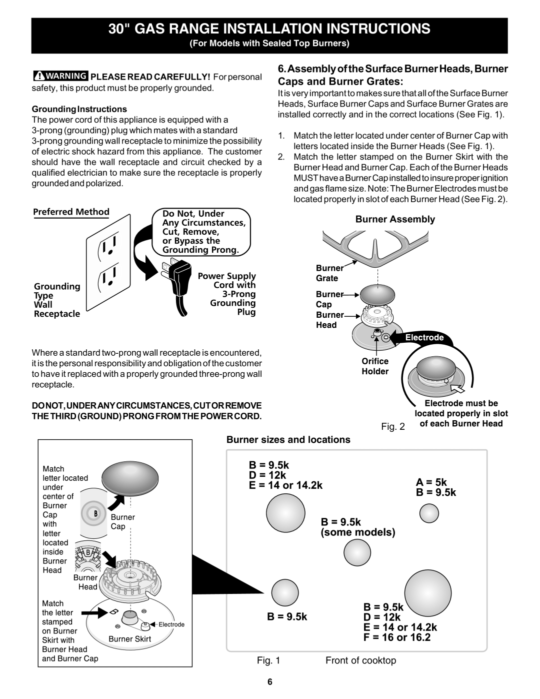
6.Assembly of the Surface Burner Heads, Burner Caps and Burner Grates:
It is very important to makes sure that all of the Surface Burner Heads, Surface Burner Caps and Surface Burner Grates are installed correctly and in the correct locations (See Fig. 1).
1.Match the letter located under center of Burner Cap with letters located inside the Burner Heads (See Fig. 1).
2.Match the letter stamped on the Burner Skirt with the Burner Head and Burner Cap. Each of the Burner Heads MUST have a Burner Cap installed to insure proper ignition and gas flame size. Note: The Burner Electrodes must be located properly in slot of each Burner Head (See Fig. 2).
Burner Assembly
Where a standard
DONOT,UNDERANYCIRCUMSTANCES,CUTORREMOVE
THE THIRD (GROUND) PRONG FROM THE POWER CORD.
Fig. 2
Burner sizes and locations
Fig. 1 | Front of cooktop |
6