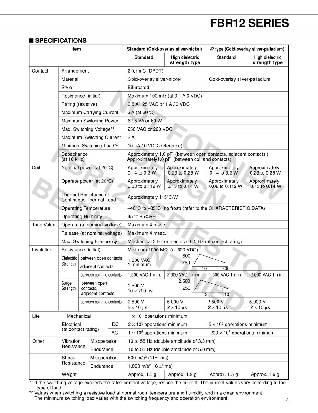
FBR12 SERIES
■SPECIFICATIONS
| Item |
|
|
|
|
| Standard |
|
|
| |||||||||||||||
|
|
|
|
|
|
|
|
|
|
|
|
|
|
|
|
|
|
|
|
|
|
|
| ||
|
|
|
|
|
|
|
|
|
|
| Standard |
|
| High dielectric |
|
|
| Standard |
|
|
| High dielectric | |||
|
|
|
|
|
|
|
|
|
|
|
|
|
|
| strength type |
|
|
|
|
|
|
|
| strength type | |
|
|
|
|
|
|
|
|
|
|
|
|
|
|
|
|
|
|
|
|
|
|
|
| ||
Contact | Arrangement |
|
|
|
|
| 2 form C (DPDT) |
|
|
|
|
|
|
|
|
|
|
|
|
| |||||
|
|
|
|
|
|
|
|
|
|
|
|
|
|
|
|
|
|
|
|
| |||||
| Material |
|
|
|
|
|
|
|
|
|
|
|
| ||||||||||||
|
|
|
|
|
|
|
|
|
|
|
|
|
|
|
|
|
|
|
|
|
|
|
|
|
|
| Style |
|
|
|
|
|
|
|
|
| Bifurcated |
|
|
|
|
|
|
|
|
|
|
|
|
| |
|
|
|
|
|
|
|
|
|
|
|
|
|
|
|
|
|
|
|
|
|
|
| |||
| Resistance (initial) | NOT |
|
|
|
|
|
|
|
|
|
|
|
|
| ||||||||||
|
|
|
|
| Maximum 100 mΩ (at 0.1 A 6 VDC) |
|
|
|
|
|
| ||||||||||||||
| Rating (resistive) |
|
|
|
| 0.5 A 125 VAC or 1 A 30 VDC |
|
|
|
|
|
| |||||||||||||
| Maximum Carrying Current | 2 A (at 20°C) |
|
|
|
|
|
|
|
|
|
|
|
|
| ||||||||||
| Maximum Switching Power | 62.5 VA or 60 W |
|
|
|
|
|
|
|
|
|
|
|
|
| ||||||||||
|
|
|
|
|
|
|
|
|
|
|
|
|
|
|
|
|
|
|
|
|
|
| |||
| Max. Switching Voltage*1 |
|
| FOR |
|
|
|
|
| ||||||||||||||||
| 250 VAC or 220 VDC |
|
|
|
|
|
|
|
|
|
| ||||||||||||||
| Maximum Switching Current | 2 A |
|
|
|
|
|
|
|
|
|
|
|
|
| ||||||||||
| Minimum Switching Load*2 | DESIGN |
|
|
|
|
| ||||||||||||||||||
| 10 μA 10 VDC (reference) |
|
|
|
|
|
| ||||||||||||||||||
| FBR12 | Approximately 1.0 pF | (between open contacts, adjacent contacts ) | ||||||||||||||||||||||
| Capacitance |
|
|
|
|
| |||||||||||||||||||
| (at 10 kHz) |
|
|
|
|
| Approximately1.0 pF | (between coil and contacts) |
|
|
|
| |||||||||||||
Coil | Nominal power (at 20°C) | Approximately |
|
| Approximately |
|
|
| Approximately |
|
|
| Approximately | ||||||||||||
|
|
|
|
|
|
|
|
|
|
| 0.14 to 0.2 W |
|
| 0.23 to 0.25 W |
|
|
| 0.14 to 0.2 W |
|
|
| 0.23 to 0.25 W | |||
| Operate power (at 20°C) | Approximately |
|
| Approximately |
|
|
| Approximately |
|
|
| Approximately | ||||||||||||
|
|
|
|
|
|
|
|
|
|
| 0.08 to 0.112 W |
|
| 0.13 to 0.14 W |
|
|
| 0.08 to 0.112 W |
|
|
| 0.13 to 0.14 W | |||
|
|
|
|
|
|
|
|
|
|
|
|
|
|
|
|
|
|
|
|
|
|
| |||
BE | Thermal Resistance at | SERIES1,500 | NEW | ||||||||||||||||||||||
Continuous Thermal Load | Approximately 115°C/W |
| |||||||||||||||||||||||
DISCONTINIED |
|
|
|
| |||||||||||||||||||||
Operating Temperature | |||||||||||||||||||||||||
| Operating Humidity |
|
|
|
| 45 to 85%RH |
|
|
|
|
|
|
|
|
|
|
|
|
| ||||||
Time Value | Operate (at nominal voltage) | Maximum 4 msec. |
|
|
|
|
|
|
|
|
|
|
| ||||||||||||
| Release (at nominal voltage) | Maximum 4 msec. |
|
|
|
|
|
|
|
|
|
|
| ||||||||||||
| Max. Switching Frequency | Mechanical 3 Hz or electrical 0.5 Hz (at contact rating) |
|
|
|
| |||||||||||||||||||
Insulation | Resistance (initial) |
|
|
|
| Minimum 1000 MΩ (at 500 VDC) |
| TO | |||||||||||||||||
| Dielectric |
| between open contacts | 1,000 VAC |
|
|
| 750 |
|
|
|
|
|
|
|
|
| ||||||||
| Strength |
|
|
|
|
|
|
|
|
|
|
|
|
|
|
|
|
|
|
|
|
| |||
|
| adjacent contacts | 1 minimum |
|
|
|
|
|
|
|
|
|
|
|
| ||||||||||
|
|
|
|
| 10 |
| 700 |
|
|
|
| ||||||||||||||
|
|
|
|
|
|
|
|
|
|
|
|
|
|
|
|
|
|
|
|
| |||||
|
|
| between coil and contacts | 1,500 VAC 1 min. |
|
| 2,000 VAC 1 min. |
|
|
| 1,500 VAC 1 min. |
|
|
| 2,000 VAC 1 min. | ||||||||||
|
|
|
|
|
|
|
|
|
|
|
|
|
|
|
|
|
|
|
|
|
|
|
|
|
|
| Surge |
| between open |
|
|
|
| 1,500 V |
|
|
| 2,500 |
|
|
|
|
|
|
|
|
| ||||
|
|
|
|
|
|
|
|
| 1,250 |
|
|
|
|
|
|
|
|
| |||||||
| Strength |
| contacts, |
|
|
|
|
|
|
|
|
|
|
|
|
|
|
|
| ||||||
|
|
|
|
|
| 10 × 700 μs |
|
|
|
|
|
|
|
|
|
|
|
| |||||||
|
|
| adjacent contacts |
|
|
| 2 |
| 10 |
|
|
|
| ||||||||||||
|
|
|
|
|
|
|
|
|
|
|
|
| |||||||||||||
|
|
| between coil and contacts | 2,500 V |
|
| 5,000 V |
|
|
| 2,500 V |
|
|
| 5,000 V | ||||||||||
|
|
|
|
|
|
|
|
|
|
| 2 × 10 μs |
|
| 2 × 10 μs |
|
|
| 2 × 10 μs |
|
|
| 2 × 10 μs | |||
|
|
|
|
|
|
|
|
|
|
|
|
|
|
|
|
|
|
|
|
| |||||
Life | Mechanical |
|
|
|
| 1 × 10⁸ operations minimum |
|
|
|
|
|
| |||||||||||||
| Electrical |
|
| DC |
| 2 × 10⁵ operations minimum |
|
| 5 × 10⁵ operations minimum | ||||||||||||||||
| (at contact rating) |
|
|
|
|
|
|
|
|
|
|
|
|
|
|
|
|
|
|
| |||||
|
| AC |
|
| 1 × 10⁵ operations minimum |
|
| 200 × 103 operations minimum | |||||||||||||||||
|
|
|
|
|
|
|
|
|
|
| |||||||||||||||
Other | Vibration |
| Misoperation |
| 10 to 55 Hz (double amplitude of 3.3 mm) |
|
|
|
|
| |||||||||||||||
| Resistance |
|
|
|
|
|
|
|
|
|
|
|
|
|
|
|
|
|
|
|
|
|
| ||
|
| Endurance |
|
| 10 to 55 Hz (double amplitude of 5.0 mm) |
|
|
|
|
| |||||||||||||||
|
|
|
|
|
|
|
|
|
|
|
| ||||||||||||||
|
|
|
|
|
|
|
|
|
|
|
|
|
|
|
|
|
|
|
|
|
|
| |||
| Shock |
|
|
|
| Misoperation |
| 500 m/s2 (11±1 ms) |
|
|
|
|
|
|
|
|
|
| |||||||
| Resistance |
|
|
|
|
|
|
|
|
|
|
|
|
|
|
|
|
|
|
|
|
|
| ||
|
| Endurance |
|
| 1,000 m/s2 ( 6 ±1 ms) |
|
|
|
|
|
|
|
|
|
| ||||||||||
|
|
|
|
|
|
|
|
|
|
|
|
|
|
|
|
| |||||||||
| Weight |
|
|
|
|
|
|
|
|
| Approx. 1.5 g |
|
|
| Approx. 1.9 g |
|
| Approx. 1.5 g |
|
|
| Approx. 1.9 g | |||
|
|
|
|
|
|
|
|
|
|
|
|
|
|
|
|
|
|
|
|
|
|
|
|
|
|
*1 | If the switching voltage exceeds the rated contact voltage, reduce the current. The current values vary according to the |
|
*2 | type of load. |
|
Values when switching a resistive load at normal room temperature and humidity and in a clean environment. |
| |
| The minimum switching load varies with the switching frequency and operation environment. | 2 |