Chapter 5 Connectors
5 Connectors
5.1Ethernet connector (X1)
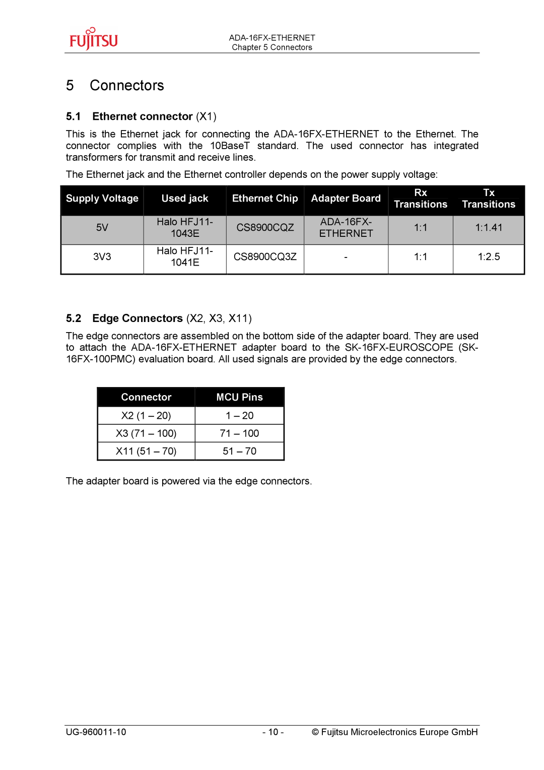
This is the Ethernet jack for connecting the
The Ethernet jack and the Ethernet controller depends on the power supply voltage:
| Supply Voltage |
|
| Used jack |
|
| Ethernet Chip |
|
| Adapter Board |
|
| Rx |
|
| Tx |
|
|
|
|
|
|
|
|
|
| Transitions |
|
| Transitions |
| ||||
|
|
|
|
|
|
|
|
|
|
|
|
|
|
|
| ||
|
|
|
|
|
|
|
|
|
|
|
|
|
|
|
|
|
|
| 5V |
|
| Halo HFJ11- |
| CS8900CQZ |
|
|
| 1:1 |
|
| 1:1.41 |
| |||
|
|
| 1043E |
|
|
| ETHERNET |
|
|
|
| ||||||
|
|
|
|
|
|
|
|
|
|
|
|
|
| ||||
|
|
|
|
|
|
|
|
|
|
|
|
|
|
|
|
| |
| 3V3 |
| Halo HFJ11- |
| CS8900CQ3Z | - |
| 1:1 |
| 1:2.5 |
| ||||||
|
| 1041E |
|
|
|
| |||||||||||
|
|
|
|
|
|
|
|
|
|
|
|
|
|
|
| ||
|
|
|
|
|
|
|
|
|
|
|
|
|
|
|
|
|
|
5.2Edge Connectors (X2, X3, X11)
The edge connectors are assembled on the bottom side of the adapter board. They are used to attach the
Connector | MCU Pins | ||
X2 | (1 – 20) | 1 | – 20 |
|
|
| |
X3 (71 – 100) | 71 | – 100 | |
|
|
| |
X11 | (51 – 70) | 51 – 70 | |
|
|
|
|
The adapter board is powered via the edge connectors.
- 10 - | © Fujitsu Microelectronics Europe GmbH |
