■MCU footprint design notes
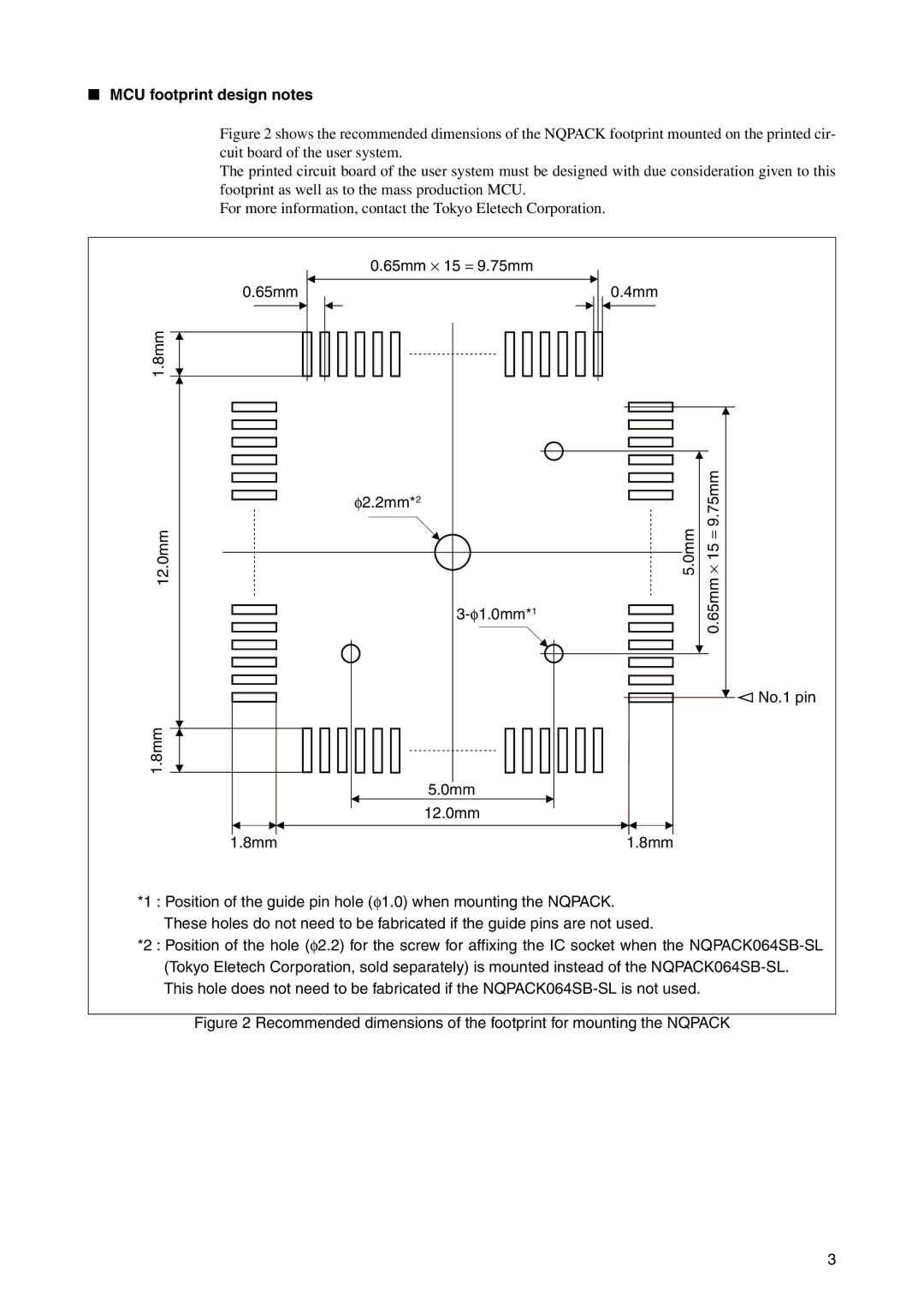
Figure 2 shows the recommended dimensions of the NQPACK footprint mounted on the printed cir- cuit board of the user system.
The printed circuit board of the user system must be designed with due consideration given to this footprint as well as to the mass production MCU.
For more information, contact the Tokyo Eletech Corporation.
| 0.65mm ⋅ 15 = 9.75mm |
|
0.65mm | 0.4mm |
|
1.8mm |
|
|
| φ2.2mm*2 | 9.75mm |
|
| |
12.0mm | 5.0mm | 0.65mm⋅ 15 = |
|
| |
|
| No.1 pin |
1.8mm |
|
|
| 5.0mm |
|
| 12.0mm |
|
1.8mm | 1.8mm |
|
*1 : Position of the guide pin hole (φ1.0) when mounting the NQPACK. These holes do not need to be fabricated if the guide pins are not used.
*2 : Position of the hole (φ2.2) for the screw for affixing the IC socket when the
Figure 2 Recommended dimensions of the footprint for mounting the NQPACK
3
