2.1 System Configuration
Connecting the
■System configuration
Connecting the
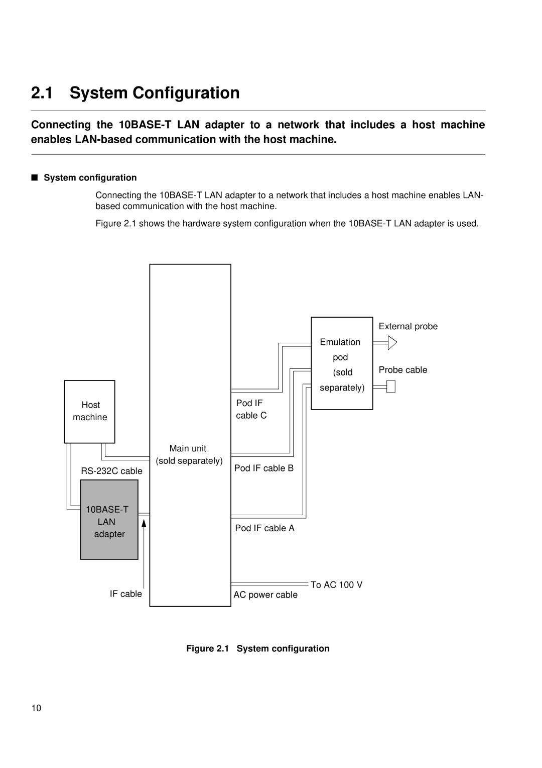
Figure 2.1 shows the hardware system configuration when the 10BASE-T LAN adapter is used.
Host machine
RS-232C cable
10BASE-T
LAN adapter
Main unit (sold separately)
Pod IF cable C
Pod IF cable B
Pod IF cable A
Emulation
pod
(sold
separately)
External probe
Probe cable
IF cable
![]() To AC 100 V AC power cable
To AC 100 V AC power cable
Figure 2.1 System configuration
10
