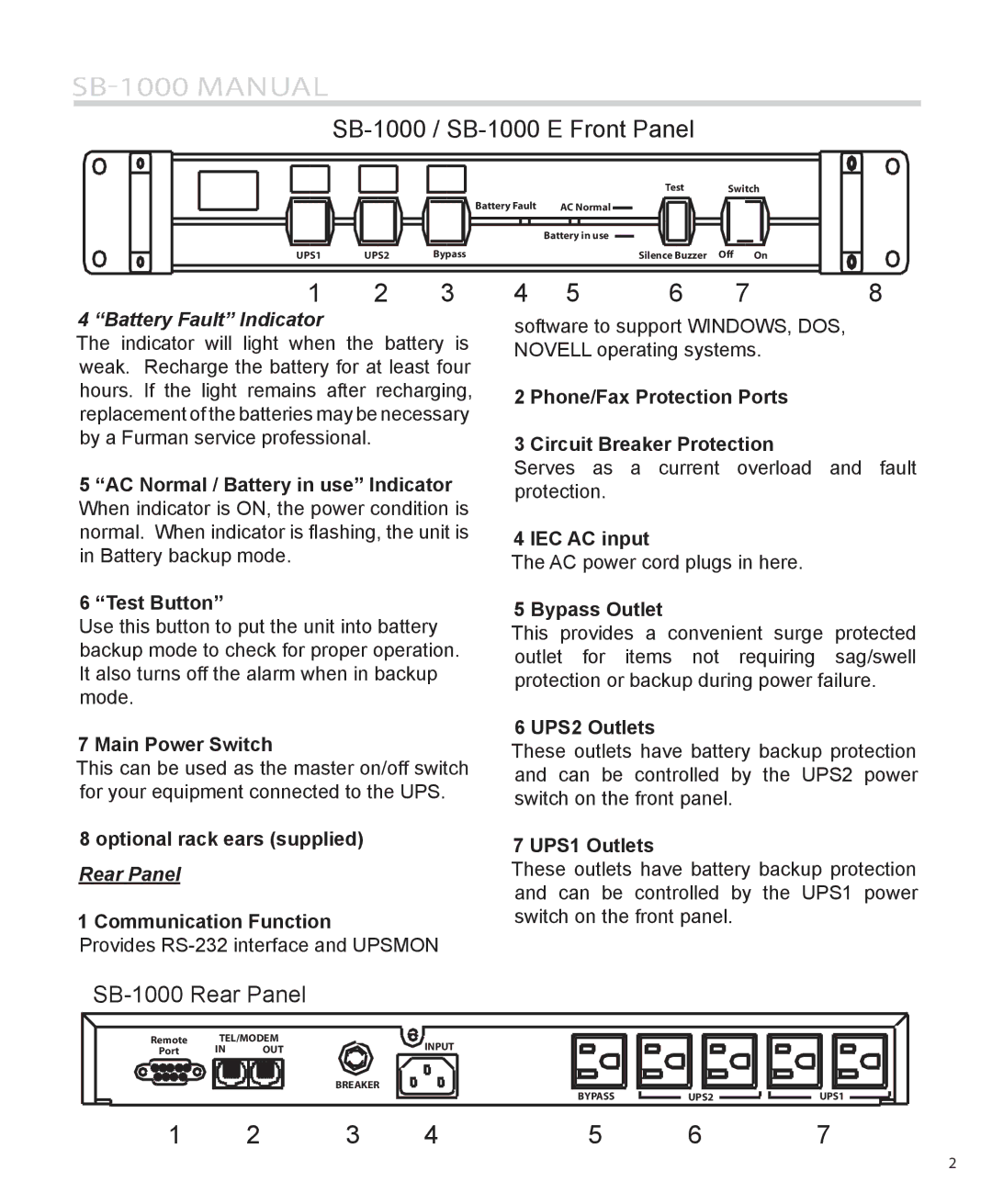
SB-1000 specifications
The Furman Sound SB-1000 is a powerful subwoofer designed to deliver exceptional low-frequency performance in various audio environments. Known for its robust build and advanced technology, the SB-1000 has become a popular choice among audio professionals and enthusiasts alike.One of the standout features of the SB-1000 is its high-efficiency Class D amplifier. The amplifier delivers a staggering output of up to 1,000 watts peak power, which ensures that the subwoofer can produce deep, punchy bass without distortion, even at high volume levels. This makes it ideal for live sound reinforcement, home theater applications, and music production.
The SB-1000 utilizes a proprietary 12-inch high-excursion driver that is engineered for controlled and precise bass response. The driver is designed to handle the rigors of professional use, with a durable construction that can withstand the demands of touring and other strenuous applications. Its large voice coil and exceptional suspension design allow the driver to move large amounts of air, resulting in dynamic bass that can fill a room or outdoor space with rich sound quality.
Another notable feature of the SB-1000 is its adjustable crossover frequency control. This allows users to tailor the subwoofer's performance to match their specific audio setup, whether it's paired with satellite speakers in a theater system or larger PA cabinets in a concert venue. The crossover control facilitates seamless integration with other speakers, ensuring a balanced and cohesive listening experience.
The subwoofer's design also addresses the importance of aesthetics and functionality. The SB-1000 features a sleek, modern enclosure made from high-quality materials that not only enhance durability but also minimize resonance and unwanted vibrations. Additionally, it is equipped with rubber feet that provide stability while preventing floor damage and vibrations from affecting other equipment.
Moreover, the SB-1000 includes multiple input options, including XLR and RCA connectors, making it versatile for various audio systems. This flexibility ensures compatibility with a wide range of audio sources, including mixers, processors, and consumer electronics.
In summary, the Furman Sound SB-1000 is a top-tier subwoofer characterized by its high-efficiency amplifier, advanced driver technology, customizable crossover settings, and robust construction. Whether used in a professional setting or for personal enjoyment, the SB-1000 delivers powerful, precise, and exhilarating bass that enhances any audio experience.

