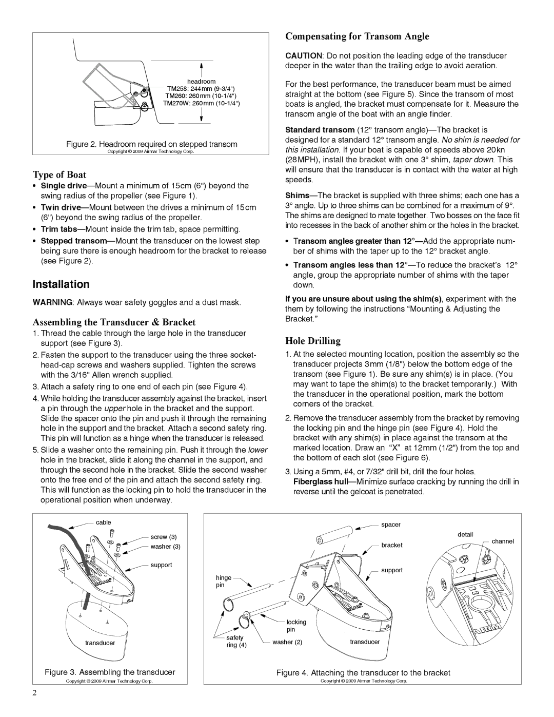
headroom |
TM258: 244mm |
TM260: 260mm |
TM270W: 260mm |
Figure 2. Headroom required on stepped transom |
Copyright © 2009 Airmar Technology Corp. |
Type of Boat
•Single
•Twin
•Trim
•Stepped
Installation
WARNING: Always wear safety goggles and a dust mask.
Assembling the Transducer & Bracket
1.Thread the cable through the large hole in the transducer support (see Figure 3).
2.Fasten the support to the transducer using the three socket-
3.Attach a safety ring to one end of each pin (see Figure 4).
4.While holding the transducer assembly against the bracket, insert a pin through the upper hole in the bracket and the support. Slide the spacer onto the pin and push it through the remaining hole in the support and the bracket. Attach a second safety ring. This pin will function as a hinge when the transducer is released.
5.Slide a washer onto the remaining pin. Push it through the lower hole in the bracket, slide it along the channel in the support, and through the second hole in the bracket. Slide the second washer onto the free end of the pin and attach the second safety ring.
This will function as the locking pin to hold the transducer in the operational position when underway.
Compensating for Transom Angle
CAUTION: Do not position the leading edge of the transducer deeper in the water than the trailing edge to avoid aeration.
For the best performance, the transducer beam must be aimed straight at the bottom (see Figure 5). Since the transom of most boats is angled, the bracket must compensate for it. Measure the transom angle of the boat with an angle finder.
Standard transom (12° transom
•Transom angles greater than
•Transom angles less than
If you are unsure about using the shim(s), experiment with the them by following the instructions “Mounting & Adjusting the Bracket.”
Hole Drilling
1.At the selected mounting location, position the assembly so the transducer projects 3mm (1/8") below the bottom edge of the transom (see Figure 1). Be sure any shim(s) is in place. (You may want to tape the shim(s) to the bracket temporarily.) With the transducer in the operational position, mark the bottom corners of the bracket.
2.Remove the transducer assembly from the bracket by removing the locking pin and the hinge pin (see Figure 4). Hold the bracket with any shim(s) in place against the transom at the marked location. Draw an “X” at 12mm (1/2") from the top and the bottom of each slot (see Figure 6).
3.Using a 5mm, #4, or 7/32" drill bit, drill the four holes. Fiberglass
cable |
screw (3) |
washer (3) |
support |
transducer |
Figure 3. Assembling the transducer |
Copyright © 2009 Airmar Technology Corp. |
2 |
|
| spacer |
|
|
|
| detail |
|
| bracket | channel |
|
|
| |
hinge |
| support |
|
|
|
| |
pin |
|
|
|
| locking |
|
|
| pin |
|
|
safety | washer (2) | transducer |
|
ring (4) |
| ||
|
|
| |
| Figure 4. Attaching the transducer to the bracket |
| |
|
| Copyright © 2009 Airmar Technology Corp. |
|