4.4 Battery
4.4.3 Battery charger (BC-6158)
Battery charger
V
28V
Fig. 4.4.4
I
20A(30A)
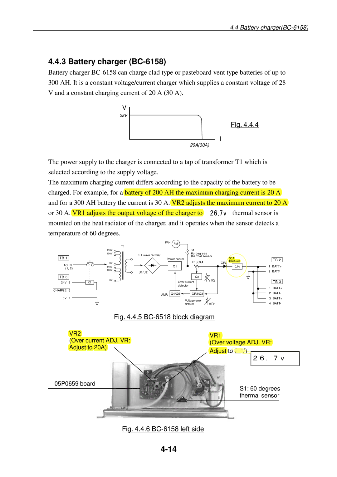
The power supply to the charger is connected to a tap of transformer T1 which is selected according to the supply voltage.
The maximum charging current differs according to the capacity of the battery to be charged. For example, for a battery of 200 AH the maximum charging current is 20 A and for a 300 AH battery the current is 30 A. VR2 adjusts the maximum current to 20 A or 30 A. VR1 adjusts the output voltage of the charger to 2826V..7vThe thermal sensor is mounted on the heat radiator of the charger, and it operates when the sensor detects a temperature of 60 degrees.
TB 1
AC IN (1, 2)
TB 3
24V 5
CHARGE 6
0V 7
K1
| FAN | FM1 |
|
|
| T1 |
|
| |
|
|
|
| |
110V |
|
| S1 |
|
100V | Full wave rectifier |
| 6o degrees |
|
|
| thermal sensor | ||
| Power conrol |
| 30A | |
0V |
|
| R1,2,3,4 | CR2 Breaker |
110V |
| Q1 |
| CP1 |
100V | U1/U2 |
|
|
|
|
|
|
| |
|
|
| Q2 | VR2 |
0V |
| Over current | ||
|
|
| ||
|
| detector |
| |
| AMP. | Q4/Q5 | CR3/Q3 |
|
|
|
|
| |
|
|
| Voltage error | VR1 |
|
|
| detctor | |
TB 2
1BATT+
2BATT-
TB 3
1BATT+
2BATT-
3BATT+
4BATT-
Fig. 4.4.5 BC-6518 block diagram
VR2 | VR1 | ||
(Over current ADJ. VR: | |||
(Over voltage ADJ. VR: | |||
Adjust to 20A) | |||
Adjust to 28V) |
| ||
| 26.7v | ||
|
| ||
05P0659 board |
|
| |
S1: 60 degrees | |||
| |||
| thermal sensor | ||
