Ground to Vehicle Chassis
Figure 2
14 AWG (black wire) J1128 TYPE GPT
- | + | 10" | Fuse |
|
Vehicle Battery![]()
Connect
Panduit
Panduit
14 AWG (red wire) J1128 TYPE GPT
CABLE RESTRAINT INFORMATION
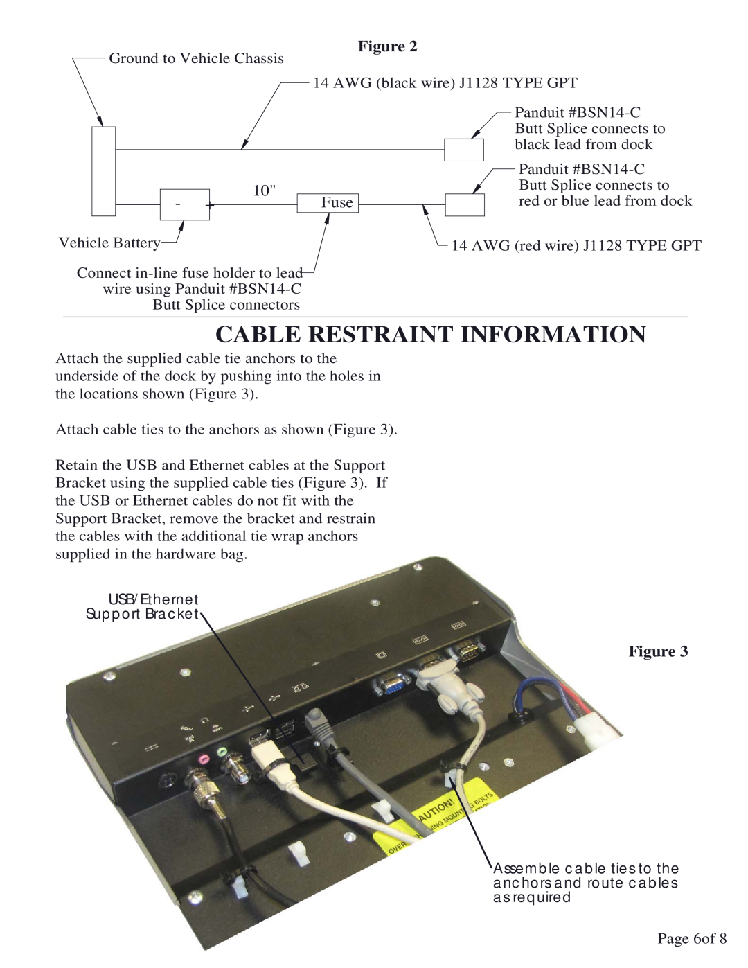
Attach the supplied cable tie anchors to the underside of the dock by pushing into the holes in the locations shown (Figure 3).
Attach cable ties to the anchors as shown (Figure 3).
Retain the USB and Ethernet cables at the Support Bracket using the supplied cable ties (Figure 3). If the USB or Ethernet cables do not fit with the Support Bracket, remove the bracket and restrain the cables with the additional tie wrap anchors supplied in the hardware bag.
USB/Ethernet
Support Bracket
Figure 3
Assemble cable ties to the anchors and route cables as required
Page 6of 8