Manuals
/
Brands
/
Power Tools
/
Battery Charger
/
Garmin
/
Power Tools
/
Battery Charger
Garmin
MC34676B manual
- page 7
1
7
14
14
Download
14 pages, 2.25 Mb
Using the Dual 28V Input Voltage Charger with Linear Regulator,
Rev. 1.0
Freescale Semiconductor
7
Layout Design
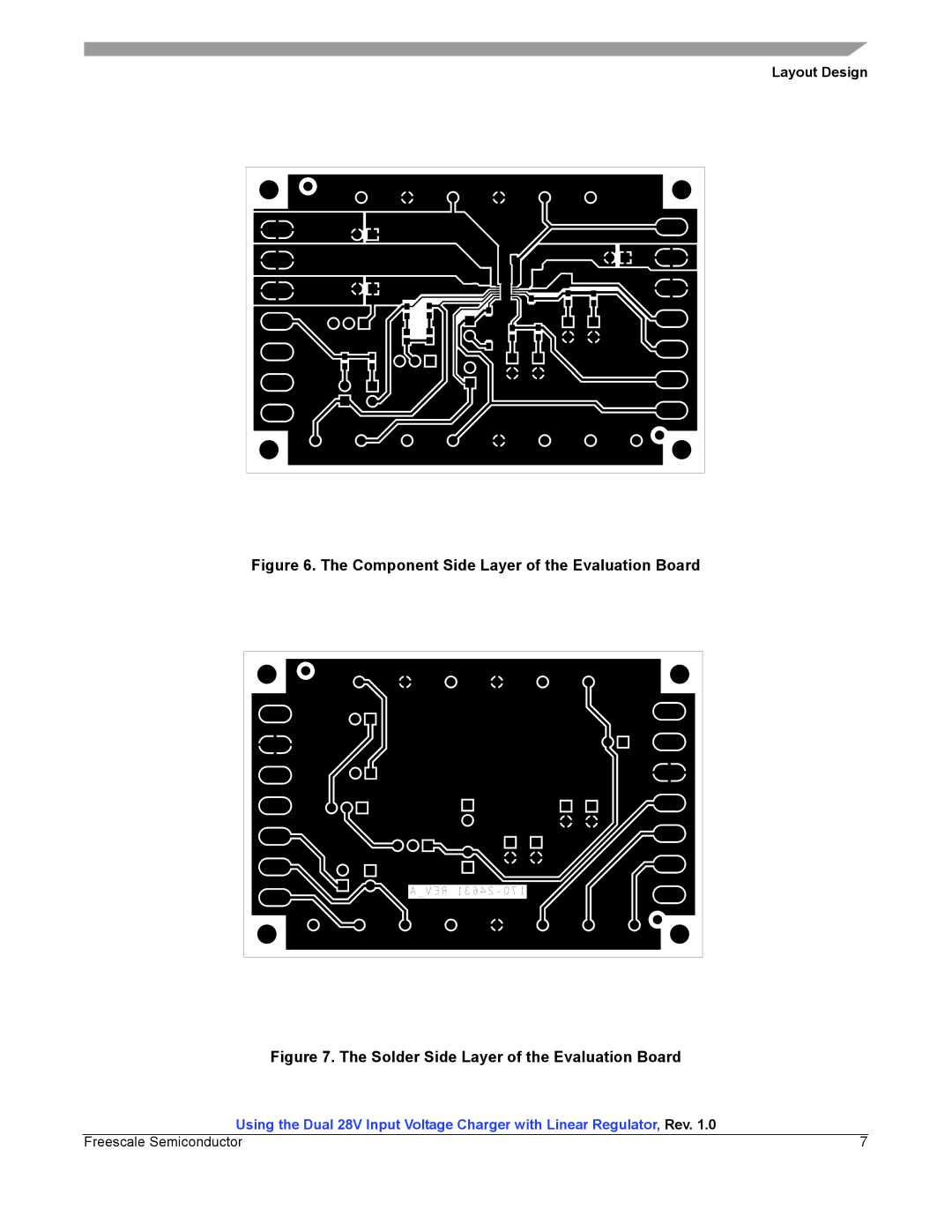
Figure
6. The Component Side Layer of the Evaluation Board
Figure
7. The Solder Side Layer of the Evaluation Board
Contents
Main
Freescale Semiconductor Users Guide
Document Number: KT34676BUG Rev. 1.0, 2/2009
1Purpose
Using the High Input Voltage Charger for Single Cell Li-Ion Batteries (KIT34676EPEVBE)
Contents
Using the Dual 28V Input Voltage Charger with Linear Regulator, Rev. 1.0
Application Diagram
3 Application Diagram
3.1 Dual-Input Standalone Charger
Figure 2. The Li-Ion Charger Embedded in the Hand Held System
Figure 1. The dual-input Li-Ion Charger
3.2 Embedded Charger
4 Evaluation Board Specification
Figure 3. The Schematic Circuit of the Evaluation Board
5 Component Selection
5.1 Input capacitors C1 and C3
5.2 Output capacitors C4 and C5
5.3 AC CC-mode charge current setting resistors R1, R2, and R3
5.4 USB CC-mode charge current setting resistors R8 and R9
5.5 End-of-charge current setting resistors R10 and R11
Table 2. The USB CC-mode Charge Current Settings
Table 3. The EOC Current Settings
Page
Page
6.2 Layout considerations
7 Evaluation Board Configuration
7.1 Pin Headers
Table 4. The Default Settings of the Pin Headers
7.2 Connector Pads
Table 4. The Default Settings of the Pin Headers
7.3 Test Points
8 Test Setup with the Evaluation Board
Figure 8. The AC Charger Set Up for the Evaluation Board
Figure 9. The USB Charger Set Up for the Evaluation Board
Using the Dual 28V Input Voltage Charger with Linear Regulator, Rev. 1.0 12 Freescale Semiconductor
Bill of Material
9 Bill of Material
Item Qty Part Reference Value DESCRIPTION Footprint Mfr PN
10 References
How to Reach Us: