Application Diagram
3 Application Diagram
3.1Dual-Input Standalone Charger
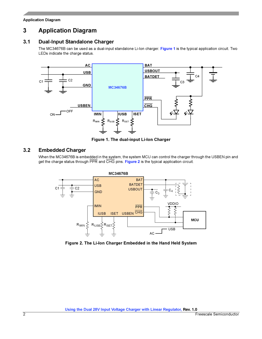
The MC34676B can be used as a
C1
AC
USB
C2
GND
USBEN
OFF
ON
MC34676B
IMIN |
| IUSB | ISET |
|
|
|
|
BAT |
|
USBOUT |
|
BATDET | C4 |
| C3 |
PPR |
|
CHG |
|
RIMIN RIUSB RISET
Figure 1. The dual-input Li-Ion Charger
3.2Embedded Charger
When the MC34676B is embedded in the system, the system MCU can control the charger through the USBEN pin and get the charge status through PPR and CHG pins. Figure 2 is the typical application circuit.
|
|
|
| MC34676B |
| |
|
| AC |
|
| BAT |
|
C1 | C2 | USB |
|
| BATDET |
|
|
| USBOUT | C4 | |||
GND |
|
| ||||
|
|
|
|
| C3 | |
|
| IMIN |
|
| PPR | VDDIO |
|
|
|
|
| ||
|
| IUSB | ISET | USBEN CHG |
| |
| RIMIN | RIUSB | RISET |
| MCU | |
|
| USB | ||||
|
|
|
|
|
| |
|
|
|
|
|
| AC |
Figure 2. The Li-Ion Charger Embedded in the Hand Held System
| Using the Dual 28V Input Voltage Charger with Linear Regulator, Rev. 1.0 |
2 | Freescale Semiconductor |
