Assembly Instructions for
Thank you for choosing the Gateway
Safety Warning: If you do not understand these directions, or have any doubts about the safety of the installation, please call a qualified contractor or contact Sanus at 800.359.5520 or www.sanus.com. We can quickly assist you with installation questions and missing or damaged parts. Replacement parts will be shipped directly to you. Check carefully to make sure there are no missing or defective parts. Never use defective parts. Improper installation may cause damage or serious injury. Do not use this product for any purpose that is not explicitly specified by Gateway or Sanus Systems. Neither Gateway nor Sanus Systems can be liable for damage or injury caused by incorrect mounting, incorrect assembly, or incorrect use.
Note: The supplied hardware is not for steel stud walls or old cinder block walls. If you are uncertain about the nature of your wall, consult an installation contractor.
Required Tools: 3/16 drill bit, 1/2” Masonry Bit for brick concrete or concrete block installations, 1/2” wrench or socket, Phillips screw driver.
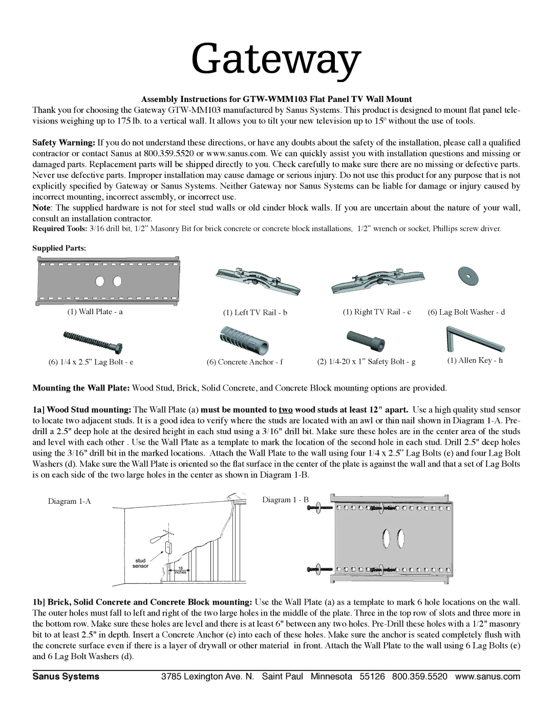
Supplied Parts:
(1) Wall Plate - a | (1) Left TV Rail - b | ) Right TV Rail - c | (6) Lag Bolt Washer - d |
(6) 1/4 x 2.5” Lag Bolt - e | (6) Concrete Anchor - f | (2) | (1) Allen Key - h |
Mounting the Wall Plate: Wood Stud, Brick, Solid Concrete, and Concrete Block mounting options are provided.
1a] Wood Stud mounting: The Wall Plate (a) must be mounted to two wood studs at least 12" apart. Use a high quality stud sensor to locate two adjacent studs. It is a good idea to verify where the studs are located with an awl or thin nail shown in Diagram
Diagram | Diagram 1 |
1b] Brick, Solid Concrete and Concrete Block mounting: Use the Wall Plate (a) as a template to mark 6 hole locations on the wall. The outer holes must fall to left and right of the two large holes in the middle of the plate. Three in the top row of slots and three more in the bottom row. Make sure these holes are level and there is at least 6" between any two holes.
Sanus Systems | 3785 Lexington Ave. N. Saint Paul Minnesota 55126 800.359.5520 www.sanus.com |