Assembly
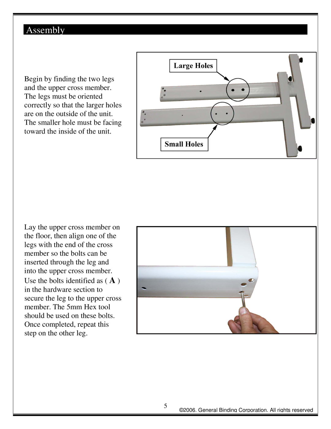
Begin by finding the two legs and the upper cross member. The legs must be oriented correctly so that the larger holes are on the outside of the unit. The smaller hole must be facing toward the inside of the unit.
Lay the upper cross member on the floor, then align one of the legs with the end of the cross member so the bolts can be inserted through the leg and into the upper cross member. Use the bolts identified as ( A ) in the hardware section to secure the leg to the upper cross member. The 5mm Hex tool should be used on these bolts. Once completed, repeat this step on the other leg.
5
©2006. General Binding Corporation. All rights reserved