Model 29298 Caller ID BedroomPhone™ with Dual-Wake Alarms and AM/FM Radio User’s Guide
Equipment Approval Information
Your telephone equipment is approved for connection to the Public Switched Telephone Network and is in compliance with parts 15 and 68, FCC Rules and Regulations and the Technical Requirements for Telephone Terminal Equipment published by ACTA.
1Notification to the Local Telephone Company
On the bottom of this equipment is a label indicating, among other information, the US number and Ringer Equivalence Number (REN) for the equipment. You must, upon request, provide this information to your telephone company.
The REN is useful in determining the number of devices you may connect to your telephone line and still have all of these devices ring when your telephone number is called. In most (but not all) areas, the sum of the RENs of all devices connected to one line should not exceed 5. To be certain of the number of devices you may connect to your line as determined by the REN, you should contact your local telephone company.
A plug and jack used to connect this equipment to the premises wiring and telephone network must comply with the applicable FCC Part 68 rules and requirements adopted by the ACTA. A compliant telephone cord and modular plug is provided with this product. It is designed to be connected to a compatible modular jack that is also compliant. See installation instructions for details.
Notes
•This equipment may not be used on coin service provided by the telephone company.
•Party lines are subject to state tariffs, and therefore, you may not be able to use your own telephone equipment if you are on a party line. Check with your local telephone company.
Visit the GE website at: www.GE.com/phones
•Notice must be given to the telephone company upon permanent disconnection of your telephone from your line.
•If your home has specially wired alarm equipment connected to the telephone line, ensure the installation of this product does not disable your alarm equipment. If you have questions about what will disable alarm equipment, consult your telephone company or a qualified installer.
US NUMBER IS IS LOCATED ON THE CABINET BOTTOM REN NUMBE IS LOCATED ON THE CABINET BOTTOM
2Rights of the Telephone Company
Should your equipment cause trouble on your line which may harm the telephone network, the telephone company shall, where practicable, notify you that temporary discontinuance of service may be required. Where prior notice is not practicable and the circumstances warrant such action, the telephone company may temporarily discontinue service immediately. In case of such temporary discontinuance, the telephone company must: (1) promptly notify you of such temporary discontinuance; (2) afford you the opportunity to correct the situation; and (3) inform you of your right to bring a complaint to the Commission pursuant to procedures set forth in Subpart E of Part 68, FCC Rules and Regulations.
The telephone company may make changes in its communications facilities, equipment, operations or procedures where such action is required in
the operation of its business and not inconsistent with FCC Rules and Regulations. If these changes are expected to affect the use or performance of your telephone equipment, the telephone company must give you adequate notice, in writing, to allow you to maintain uninterrupted service.
Interference Information
This device complies with Part 15 of the FCC Rules. Operation is subject to the following two conditions: (1) This device may not cause harmful interference; and (2) This device must accept any interference received, including interference that may cause undesired operation.
This equipment has been tested and found to comply with the limits for a Class B digital device, pursuant to Part 15 of the FCC Rules. These limits are designed to provide reasonable protection against harmful interference in a residential installation.
This equipment generates, uses, and can radiate radio frequency energy and, if not installed and used in accordance with the instructions, may cause harmful interference to radio communications. However, there is no guarantee that interference will not occur in a particular installation.
Privacy of Communications may not be ensured when using this product.
If this equipment does cause harmful interference to radio or television reception, which can be determined by turning the equipment off and on, the user is encouraged to try to correct the interference by one or more of the following measures:
•Reorient or relocate the receiving antenna (that is, the antenna for radio or television that is “receiving” the interference).
•Reorient or relocate and increase the separation between the telecommunications equipment and receiving antenna.
•Connect the telecommunications equipment into an outlet on a circuit different from that to which the receiving antenna is connected.
If these measures do not eliminate the interference, please consult your dealer or an experienced radio/television technician for additional suggestions. Also, the Federal Communications Commission has prepared a helpful booklet, “How To Identify and Resolve Radio/TV Interference Problems.” This booklet is available from the U.S. Government Printing Office, Washington, D.C. 20402. Please specify stock number 004-000-00345-4 when ordering copies.
Hearing Aid Compatibility (HAC)
This telephone system meets FCC standards for Hearing Aid Compatibility.
Licensing
Licensed under US Patent 6,427,009.
FCC RF Radiation Exposure Statement
This equipment complies with FCC RF radiation exposure limits set forth for an uncontrolled environment. This equipment should be installed and operated with a minimum distance of 20 centimeters between the radiator and your body. This transmitter must not be co-located or operated in conjunction with any other antenna or transmitter.”
Introduction
CAUTION: When using telephone equipment, there are basic safety instructions that should always be followed. Refer to the IMPORTANT SAFETY INSTRUCTIONS provided with this product and save them for future reference.
Before You Begin
Parts Checklist
Make sure your package includes the following items:
Base | | Handset |
| AC power | cord |
| |
Telephone line | adaptor | Handset |
cord | | |
Telephone Jack Requirements
To use this phone, you need an RJ11C type | Wall plate |
modular telephone jack, which might look like | |
the one pictured here, installed in your home. If | Modular |
you don’t have a modular jack, call your local | telephone |
phone company to find out how to get one | line jack |
|
installed. | |
Important Installation Guidelines
•Install telephone near both a telephone (modular) jack and an electrical power outlet.
•Avoid sources of noise, such as a window by a busy street, and electrical noise, such motors, microwave ovens, and fluorescent lighting.
•Avoid heat sources, such as heating air ducts, heating appliances, radiators, and direct sunlight.
•Avoid areas of excessive moisture or extremely low temperature.
•Avoid dusty locations.
•Avoid other cordless telephones or personal computers.
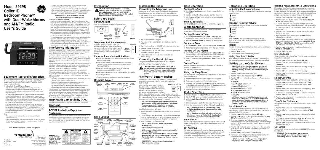
Handset Layout
| CID 5or6 | dial | display | delete | VOLUME | menu |
| (Caller ID | (button) | | | (button) | (switch) | (button) |
| button) | | | | | | |
| */tone | | | | | mem | |
| | | | | (memory | |
| (button) | | ghi | jkl | mno | button) | |
| | | pqrs | tuv | wxyz | | |
| store | | | | | redial | |
| (button) | | tone | oper | | (button) | |
| | | store | mem | redial | | |
| flash | | | flash | | | |
| | | | | | |
| (button) | | | | | | |
| Base Layout | | | alarm 1 | | |
| alarm 2 | ringer | | set time/alarm |
| off/buzzer/radio (switch) | off/buzzer/radio |
| (switch) |
| (switch) | | | | (switch) |
| | | | | |
AM/FM (switch) 
Installing the Phone
Connecting the Telephone Line
Choose the best location to install your telephone. Your telephone should be placed on a level surface, such as a desk or table top.
1.Plug one end of the straight telephone line cord into the PHONE LINE jack on the base.
2.Plug the other end into a wall jack.
3.Plug one end of the coiled handset cord into the jack on the handset.
4.Plug the other end into the HANDSET jack on the back of the base.
5.Place the handset on the base cradle.
6.Set the RINGER and DISPLAY BRIGHTNESS switches on the back of the base to the desired settings.
7.Set the VOL switch on the side of the handset to the desired setting..
Connecting the Electrical Power
1.Plug one end of the power supply cord into the back of the base.
2.Plug the other end into an electrical outlet.
CAUTION: To reduce risk of personal injury, fire, or damage use only the 5-2836 power adaptor listed in the user’s guide. This power adaptor is intended to be correctly orientated in a vertical or floor mount position.
“No Worry” Battery Backup
This telephone is equipped with a memory holding system | | |
powered by a customer-installed 9-volt alkaline battery | - | |
(not included). | Battery clip | + |
When electrical power is interrupted, or | | |
Battery | - | |
the electrical line is unplugged, the battery | + |
operates the clock to retain the time of day | Type | 9V | |
and alarm settings in memory. When the | NEDA | | |
unit is running on battery power, the digital | 1604A |
|
display does not light up; however, if wake time occurs during the power interruption, the alarm buzzer sounds (regardless of the type of alarm tone selected) if remaining battery power is adequate. Normal operation resumes after electrical power is restored.
NOTE: The battery power indicator illuminates if the battery power level is low or if no battery is installed. Please replace/install the batteries as soon as possible in order to maintain Caller ID operation.
Install the backup battery as follows:
1.Remove the battery compartment cover located on the bottom of the base.
2.Connect a fresh 9-volt alkaline battery (not included). Interlock the large and small contacts on the battery clip and the battery. Once connected, place the battery inside the battery compartment.
3.Replace the battery compartment cover.
NOTE: 9V Alkaline (NEDA 1604A) batteries are recommended.
NOTE: If battery is not installed:
Base Operation
Setting the Clock
1.Slide the set time /alarm switch to clock. The screen flashes the setting time.
2.Press the <rev/fwrd> or fwrd >> button to set the clock time.
3.Slide the set time/alarm switch to lock. The screen displays the current time.
Display Backlight
Use the brightness switch to select the desired setting: high or low.
Alarm Operation
The 29298 is equipped with two alarms. The alarms can be set independently to either radio or buzzer.
Setting the Alarm Time
1.Slide the set time /alarm switch to alarm 1 or alarm 2. The corresponding alarm time will be shown on the clock display.
2.Press the <rev/fwrd> or fwrd >> button to set the alarm time.
Set Alarm Tone
1.Slide the alarm 1 or alarm 2 switch to choose radio, buzzer or off.
2.The corresponding alarm ON indicator on the display illuminates.
Turning Off the Alarms
1.To turn off the alarm, press the off side of the radio on/off button once. Alarm is still active and will be delivered when alarm time is reached again. Alarm ON indicator will remain illuminated.
2.Alarm is turned off by sliding the alarm 1 or alarm 2 switch to “off” setting.
Snooze Timer
After the wake mode is activated, you can silence for 6 minutes by pressing the SNOOZE button.
You may use the snooze feature repeatedly.
Using the Sleep Timer
Use the sleep timer to play the radio up to 59 minutes and then have it shut off automatically.
1.Press the sleep button once to activate the radio sleep timer.
2.The timer can be adjusted from 59 minutes to 1 minute.
3.To set sleep time, press and hold the sleep button. The time shown on the clock display will decrease. Then release the sleep button when the desired length of time is shown on the clock display.
4.Press the off button to de-activate the sleep function.
Radio Operation
1.Press the on side of the radio on/off button to turn the radio on.
2.Slide the AM/FM switch to select the desired broadcast band.
3.Rotate the radio channel tuning knob to select a radio station / frequency.
4.Rotate the volume -/+ control knob to adjust the listening level.
5.To turn the radio off, press the off side of the radio on/off button.
Note: You can also turn on the radio after lifting up the handset by pressing the on side of the radio on/off button.
Note: The Radio broadcast will automatically turn off when you picked up the handset. Broadcast will resume when you replace the handset on cradle.
AM Antenna
A built-in antenna eliminates the need for an outside antenna for AM reception. Moving the unit slightly may improve reception of distant AM signals.
FM Antenna
Telephone Operation
Adjusting the Ringer Volume
You may control the ringer volume level with the switch located on the side of the base.
 = loud
= low = off
Handset Receiver Volume
Use the volUME switch on the rear of the handset to adjust the handset receiver volume.
= high
 = mid
= mid  = low
= low
Flash
Press the flash button to activate customer calling services, such as call transfer, which are services provided by your local phone company.
Redial
To redial the last number called (up to 32 digits), use the redial feature.
1.Pick up the handset.
2.Press the redial button.
3.The last number called is automatically redialed.
Using One Touch Redial
If the last call you dialed was busy, you can redial it immediately by just pressing the redial button and without hanging up the handset.
Setting Up the Caller ID Menu
IMPORTANT: Do not plug the telephone into the wall jack while setting up the Caller ID menu because an incoming call may invalidate the information not yet saved.
1. | Place the handset in the cradle on the base. |
2. | Press the menu button. the screen displays SET ^ OR . |
3.Press the CID5 or 6 button to scroll among the 7 menu screens, which are:
•SET ^ OR
•Local Area Code (default ” - - -”)
•Regional AC’s-1(default “- - - - - - - - -”)
•CID LANGUAGE (default English)
•SELECT CONTRAST (default 3)
•T/P DIAL MODE (default tone)
•EXIT SETUP
NOTE: You may press the dial button anytime to exit the Caller ID Set Up menu. If no buttons are pressed within 10 seconds, the phone automatically exits the Caller ID Set Up menu and returns to the NO CALLS summary screen.
Local Area Code
The telephone uses the programmed area code to determine the number format to display when a valid Caller ID signal is received. It is also used for the Dialback feature.
1. | Press the menu button. the screen displays SET ^ OR . |
2. | Press the CID5 or 6button until the screen displays LOCAL AREA |
| CODE, The default setting is ”_ _ _” . |
3. | To enter or change the area code, press the menu button. The |
| screen displays the area code stored in memory. The left-most digit, |
| or a minus sign (-) flashes, indicating the unit is ready to accept the |
| area code entry. |
4. | Press the CID 6 button to select a number from 0-9 in ascending |
| order. Or press the CID 5 button to select numbers from 9-0 in |
Regional Area Codes for 10-Digit Dialling
Like the Local Area Code, the telephone uses the programmed area codes to determine the number format to display when a valid Caller ID signal is received. Calls that match any of the programmed regional area codes are displayed as 10 digits. This is helpful in areas that have multiple or overlapping area codes and require 10-digit dialling.
1.Press the menu button. the screen displays SET ^ OR .
.
2.Press the CID5 or 6 button until the screen displays REGIONAL AC’S-1:The default setting is “_ _ _ _ _ _ _ _ _” .
3.To enter or change the area code, press the menu button. The screen displays the area code stored in memory. The left-most digit, or minus sign (-), flashes, indicating the unit is ready to accept the area code entry.
4.Press the CID 5 button to select a number from 9-0 for the first digit of the area code.
5.When the desired digit is flashing, press the menu button to advance to the next digit.
6.Press the menu button again to enter the next three-digit regional area code and repeat steps 4 and 5 until all the REGIONAL AC’S-1(RAC#1) and REGIONAL AC’S-2(RAC#1) are entered. A total of 6 sets of Regional Area Codes may be entered.
7.Press the menu button to store the setting and return to the REGIONAL AREA CODE setting.
8.Press the dial button to exit.
CID Language
This setting allows you to display Caller ID display prompt messages in English, French or Spanish.
1. Press the menu button. the screen displays SET ^ OR .
2.Press the CID5 or 6 button until the screen displays CID LANGUAGE.
3.Press the menu button to show the current language setting. The default is “English”.
4.Press the CID5 or 6 button to change the language.
5.Press the menu button to store the language and return to the CID LANGUAGE setting.
Select Contrast
This adjustment allows you to adjust the contrast of the display. 1. Press the menu button until the screen displays SET ^ OR .
2.Press the CID5 or 6 button until the screen displays SELECT CONTRAST.
3.Press the menu button to show the current contrast setting. There are 5 levels of contrast, with the default set to 3.
4.To decrease the contrast, press the CID 5 button to increase the contrast, press the CID 6 button.
5.Press the menu button to store the contrast setting and return to the SELECT CONTRAST setting.
Tone/Pulse Dial Mode
This adjustment allows you to select tone (touch-tone) or pulse (rotary) dialling.
1. Press the menu button until the screen displays SET ^ OR .
2.Press the CID5 or 6 button until the screen displays T/P DIAL MODE.
3.Press the menu button to show the current dial mode. The default is “TONE”.
4.To change the dialling mode, press the CID 5 or 6 button. The display will alternate between the two dialling modes.
5.Press the menu button to store the dialling mode and return to the T/P DIAL MODE setting.
Exit Setup