INSTALLATION INSTRUCTIONS
EXHAUST
Installation and service must be performed by a qualified installer, service agency or the gas supplier. IMPORTANT: Have your dryer installed properly.
NOTE: The WARNING and IMPORTANT instructions appearing in this manual are not meant to cover all possible conditions and situations that may occur. It must be understood that common sense, caution, and carefulness are factors that CANNOT be built into the dryer. These factors MUST BE supplied by the person(s) installing, maintaining, or operating the dryer.
Failure to install, maintain, and/or operate this machine according to the manufacturer’s instructions may result in conditions which can produce bodily injury and/or property damage.
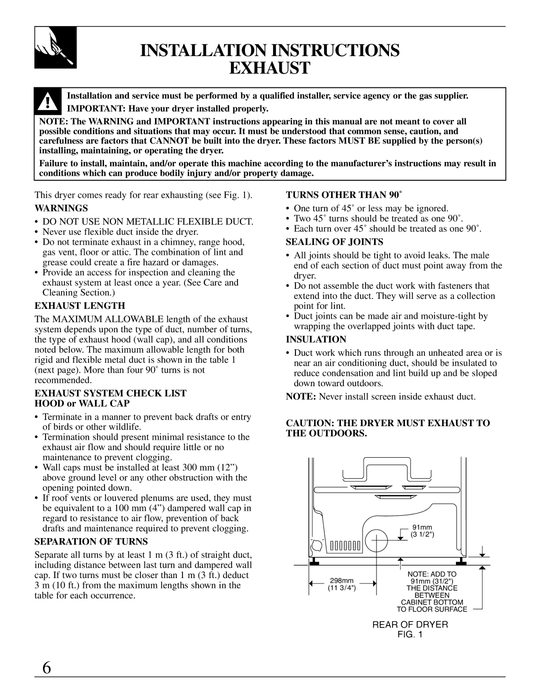
This dryer comes ready for rear exhausting (see Fig. 1).
WARNINGS
•DO NOT USE NON METALLIC FLEXIBLE DUCT.
•Never use flexible duct inside the dryer.
•Do not terminate exhaust in a chimney, range hood, gas vent, floor or attic. The combination of lint and grease could create a fire hazard or damages.
•Provide an access for inspection and cleaning the exhaust system at least once a year. (See Care and Cleaning Section.)
EXHAUST LENGTH
The MAXIMUM ALLOWABLE length of the exhaust system depends upon the type of duct, number of turns, the type of exhaust hood (wall cap), and all conditions noted below. The maximum allowable length for both rigid and flexible metal duct is shown in the table 1 (next page). More than four 90˚ turns is not recommended.
EXHAUST SYSTEM CHECK LIST
HOOD or WALL CAP
•Terminate in a manner to prevent back drafts or entry of birds or other wildlife.
•Termination should present minimal resistance to the exhaust air flow and should require little or no maintenance to prevent clogging.
•Wall caps must be installed at least 300 mm (12”) above ground level or any other obstruction with the opening pointed down.
•If roof vents or louvered plenums are used, they must be equivalent to a 100 mm (4”) dampered wall cap in regard to resistance to air flow, prevention of back drafts and maintenance required to prevent clogging.
SEPARATION OF TURNS
Separate all turns by at least 1 m (3 ft.) of straight duct, including distance between last turn and dampered wall cap. If two turns must be closer than 1 m (3 ft.) deduct 3 m (10 ft.) from the maximum lengths shown in the table for each occurrence.
TURNS OTHER THAN 90˚
•One turn of 45˚ or less may be ignored.
•Two 45˚ turns should be treated as one 90˚.
•Each turn over 45˚ should be treated as one 90˚.
SEALING OF JOINTS
•All joints should be tight to avoid leaks. The male end of each section of duct must point away from the dryer.
•Do not assemble the duct work with fasteners that extend into the duct. They will serve as a collection point for lint.
•Duct joints can be made air and
INSULATION
•Duct work which runs through an unheated area or is near an air conditioning duct, should be insulated to reduce condensation and lint build up and be sloped down toward outdoors.
NOTE: Never install screen inside exhaust duct.
CAUTION: THE DRYER MUST EXHAUST TO THE OUTDOORS.
| 91mm |
| (3 1/2") |
298mm | NOTE: ADD TO |
91mm (31/2") | |
(11 3/4") | THE DISTANCE |
| BETWEEN |
CABINET BOTTOM
TO FLOOR SURFACE
6