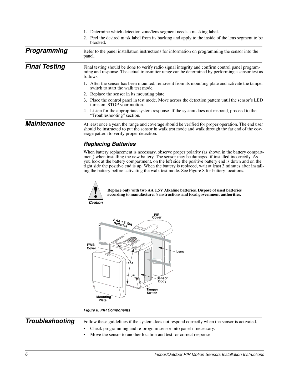
60-639-95R, 60-639-43-EUR, 60-639-43-EUR-OD, 60-639-95R-OD specifications
The GE 60-639-43-EUR-OD and its associated models, including the 60-639-43-EUR, 60-639-95R, and 60-639-95R-OD, represent a significant advancement in engineering solutions from General Electric, designed to meet diverse industrial needs. These models are recognized for their robust functionality and reliability in demanding operational environments.One of the main features of these models is their versatility in application. They are engineered to cater to a variety of sectors including manufacturing, transportation, and energy. Their adaptability allows them to be seamlessly integrated into existing systems, offering enhanced performance without requiring extensive modifications.
The GE 60-639 series is fortified with advanced technologies that enhance efficiency and productivity. Key among these technologies is their use of smart monitoring systems, which provide real-time data and insights into performance metrics. This feature not only aids in predictive maintenance, minimizing downtime but also optimizes the overall workflow.
In terms of characteristics, these models are designed with a focus on energy efficiency. They utilize innovative power management technologies that reduce energy consumption while maintaining peak performance. This not only lowers operational costs but also aligns with global sustainability efforts aimed at reducing carbon footprints.
Moreover, the build quality of the GE 60-639 series is exceptional. They are constructed using high-grade materials that ensure durability and resilience against harsh operational conditions. This ruggedness translates into longer service life and lower replacement costs, making them a wise investment for businesses.
The user interface of these models is intuitive, allowing for easy operation and management. With streamlined controls and comprehensive diagnostic features, users can effectively monitor and manage system performance with minimal training.
In conclusion, the GE 60-639-43-EUR-OD, along with its counterparts, exemplifies GE’s commitment to innovation and reliability. With their versatile application, advanced technologies for efficiency, and robust construction, these models stand out as ideal solutions for modern industrial challenges. Organizations looking to enhance their operational capabilities would benefit significantly from integrating these reliable systems into their operations.

