Bottom
Bead
Cushion Mount Detail

Installation Instructions

1COMPONENTS AND INSTALLATION

COMPONENTS


*Stopper


*Removable


Splash Guard


Sink Flange


Rubber Sink


Flange Gasket

Sink Flange


Sink


Assembly

Fiber Gasket


Support Ring


(Note Arrows


Indicating Up)


Mount Ring


Tightening Ears


Cushion Mount

Groove

Dishwasher


Discharge Inlet


Elbow Gasket

Hopper


Disposer


Screws


Elbow

Discharge

End Bell

Flange


Elbow

(Electrical


Rating Label


Connections)


in This Area


*Not used with batch feed model

INSTALLATION OF SINK FLANGE

(Read completely before starting.)

Correctly Installed Sink Flange

Sink Flange

Rubber Gasket

Fiber Gasket

Sink


Support Ring

Bottom Bead of

Sink Flange

Cushion Mount


Open Area No Obstruction

Mount Ring should be free


to move up and down

Groove

Cushion Mount

Bottom Bead

(shown for proper orientation)

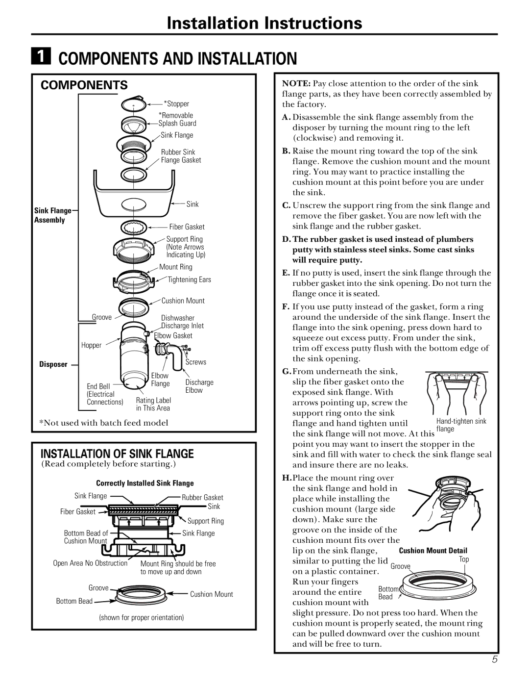
NOTE: Pay close attention to the order of the sink flange parts, as they have been correctly assembled by the factory.

A. Disassemble the sink flange assembly from the disposer by turning the mount ring to the left (clockwise) and removing it.

B. Raise the mount ring toward the top of the sink flange. Remove the cushion mount and the mount ring. You may want to practice installing the cushion mount at this point before you are under the sink.

C. Unscrew the support ring from the sink flange and remove the fiber gasket. You are now left with the sink flange and the rubber gasket.

D. The rubber gasket is used instead of plumbers putty with stainless steel sinks. Some cast sinks will require putty.

E. If no putty is used, insert the sink flange through the rubber gasket into the sink opening. Do not turn the flange once it is seated.

F.If you use putty instead of the gasket, form a ring around the underside of the sink flange. Insert the flange into the sink opening, press down hard to squeeze out excess putty. From under the sink, trim off excess putty flush with the bottom edge of the sink opening.

G.From underneath the sink,


slip the fiber gasket onto the


exposed sink flange. With


arrows pointing up, screw the


support ring onto the sink

Hand-tighten sink

flange and hand tighten until

the sink flange will not move. At this flange point you may want to insert the stopper in the

sink and fill with water to check the sink flange seal and insure there are no leaks.

H.Place the mount ring over

the sink flange and hold in place while installing the cushion mount (large side down). Make sure the

groove on the inside of the cushion mount fits over the lip on the sink flange,

similar to putting the lid GrooveTop on a plastic container.

Run your fingers around the entire

cushion mount with

slight pressure. Do not press too hard. When the cushion mount is properly seated, the mount ring can be pulled downward over the cushion mount and will be free to turn.

5

Page 5
Image 5
GE GFB1000F, GFC700F, GFC500F, GFC1000F, GFB700F owner manual Components and Installation, Installation of Sink Flange

GFB700F, GFC1000F, GFC500F, GFC700F, GFB1000F specifications

General Electric (GE) has established itself as a leader in the aviation and energy sectors, offering an impressive array of high-performance gas turbines. Models like the GE GFB1000F, GFC700F, GFC500F, GFC1000F, and GFB700F stand as testaments to the company’s commitment to innovative engineering and advanced technology. These turbines are designed to deliver exceptional efficiency, reliability, and flexibility, catering to various industrial applications.

The GE GFB1000F turbine is characterized by its efficiency and power output, making it suitable for both base load and peak load applications. It features advanced aerodynamics and materials technology that allow it to operate at high temperatures, resulting in increased performance. The turbine also incorporates digital controls for enhanced operational efficiency and reliability.

The GFC700F model is known for its adaptability in various operational environments. It boasts a robust design that can handle fluctuating load demands without compromising efficiency. The GFC700F integrates advanced combustion technology, which minimizes emissions and ensures compliance with stringent environmental regulations.

For lower output needs, the GFC500F turbine offers a highly efficient solution with a compact footprint. Its design emphasizes ease of maintenance and operational flexibility, making it an ideal choice for smaller power plants and industrial applications. The GFC500F utilizes a simple cycle configuration, allowing for quick start-up times and operational adaptability.

The GFC1000F serves as a middle ground, delivering a balanced mix of efficiency and power for medium to large-scale applications. It features advanced sensor technology and digital controls that optimize performance in real-time, ensuring maximum output while minimizing fuel consumption.

Finally, the GFB700F represents a versatile option with a focus on flexibility and investment protection. This turbine supports a wide range of fuels and operational modes, enhancing its appeal to customers seeking a versatile energy solution. Its advanced monitoring systems allow for proactive maintenance strategies, further reducing downtime and operational costs.

Collectively, these gas turbines from GE reflect the company’s forward-thinking approach, harnessing cutting-edge technology to meet the ever-evolving demands of the energy sector. Their shared focus on efficiency, reduced emissions, and operational flexibility positions them as frontrunners in sustainable energy generation.