Installation Instructions
14SCREW IN PARTWAY
Drive a mounting screw (from the hardware packet) partway into each center of the narrow neck of the keyhole slots marked on the cabinet bottom.
15OPTIONAL POWER CORD KIT JXHC1
An optional Power Cord Connection Kit, model JXHC1, is available at extra cost from your GE supplier for installation using a standard
C | Cabinet |
|
L |
| |
|
| |
73⁄4″ |
| wall outlet |
11⁄4″ | (if using cord | |
| connection) |
13⁄4″ dia. clearance hole for optional power supply location
NOTE: If using optional Power Cord Kit JXHC1, feed the power cord through the hole in the top cabinet while raising the hood. Loop any excess length of cord and tie away with a suitable tape or tie.
16FEED IN WIRES
Lift the hood into position and feed the house wiring through the wiring knockout.
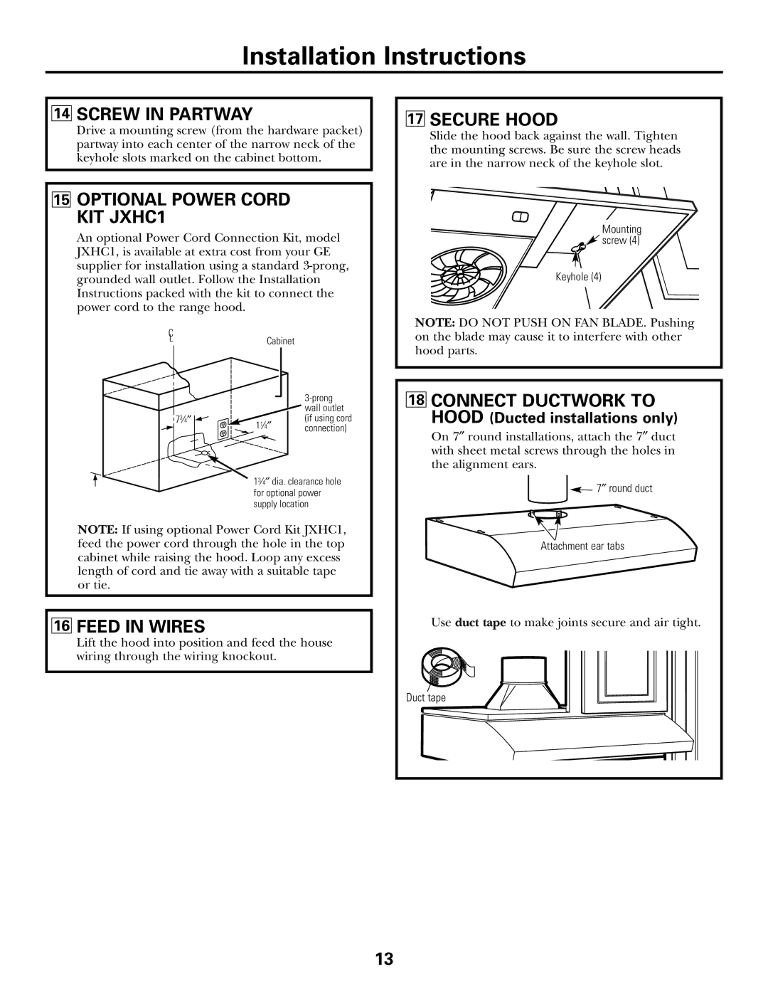
17SECURE HOOD
Slide the hood back against the wall. Tighten the mounting screws. Be sure the screw heads are in the narrow neck of the keyhole slot.
Mounting
![]() screw (4)
screw (4)
Keyhole (4)
NOTE: DO NOT PUSH ON FAN BLADE. Pushing on the blade may cause it to interfere with other hood parts.
18CONNECT DUCTWORK TO HOOD (Ducted installations only)
On 7″ round installations, attach the 7″ duct with sheet metal screws through the holes in the alignment ears.
![]() 7″ round duct
7″ round duct
Attachment ear tabs
Use duct tape to make joints secure and air tight.
Duct tape
13