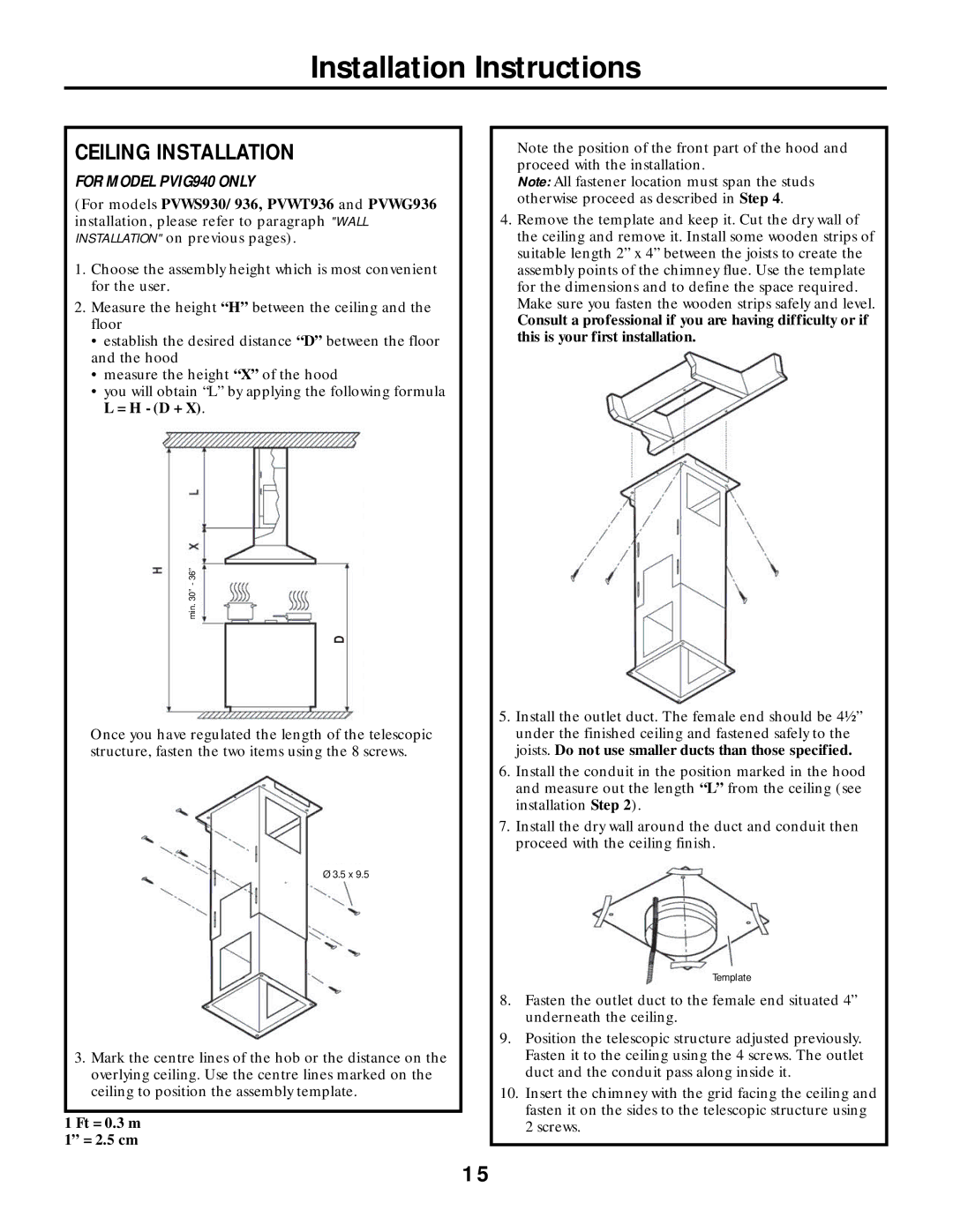
PVWS936, PVIG940, PVWG936, PVWS930, PVWT936 specifications
The GE PVWS936, PVWT936, PVWS930, PVWG936, and PVIG940 are part of General Electric's advanced lineup of water and wastewater management solutions. These models reflect GE's commitment to delivering innovative technology, energy efficiency, and operational reliability in the realm of water treatment.One of the standout features of the GE PVWS936 and PVWT936 is their robust filtration capabilities, designed to handle a variety of water quality issues. These models incorporate advanced membrane technology which enhances the efficiency of contaminant removal while minimizing energy consumption. This leads to significant cost savings in chemical usage and maintenance, a valuable proposition for municipalities and industrial applications alike.
The PVWS930 model emphasizes versatility and ease of operation. It is equipped with user-friendly interfaces and remote monitoring capabilities, allowing operators to track performance metrics in real-time. This feature not only streamlines operations but also aids in proactive maintenance, reducing downtime and extending the life of the equipment.
Another notable characteristic is observed in the PVWG936, which boasts a compact design without compromising on performance. It is engineered to maximize space utilization in treatment facilities, making it ideal for sites where footprint is a concern. This model is particularly well-suited for urban settings where space limitations are increasingly becoming an operational hurdle.
The GE PVIG940 focuses on integrated growth with an emphasis on sustainability. This model goes beyond just treating water; it's designed to promote environmental stewardship by incorporating energy-efficient components and reducing carbon footprint. Its ability to integrate with renewable energy sources underscores GE's commitment to sustainable development in water management.
All these models share common technological advancements such as enhanced automation, data analytics, and IoT integration. The data analytics capabilities allow operators to make informed decisions based on real-time data, leading to improved operational efficiencies. Furthermore, the IoT integration enables predictive maintenance, ensuring that systems are functioning optimally and reducing the likelihood of unexpected failures.
Overall, the GE PVWS936, PVWT936, PVWS930, PVWG936, and PVIG940 are engineered to meet the demands of modern water treatment processes. Their advanced features, emphasis on energy efficiency, and commitment to sustainability make them exceptional choices for both municipal and industrial applications. As water scarcity and quality issues continue to challenge communities worldwide, these models present effective solutions that align with the best practices in environmental management.

