INTRODUCTION
Congratulations on purchasing a Gemini Platinum Series model
FEATURES
•Cut Feature for Low, Mid and High of each channel
•BPM Display
•3 Stereo channels (3 Phono, 3 Line and 1 Mic)
•Neutrik ComBo XLR/Jack DJ Mic.
•Low, Mid, High and Gain controls on each channel
•Beat Offset Indicators
•Master, Booth and Record outputs
•Dual mode display (Left & Right output or Channel 2 and Channel 3)
•Push button cueing with Cue/Program pan control
CAUTIONS
1.All operating instructions should be read before using this equipment.
2.To reduce the risk of electrical shock, do not open the unit. There are NO USER REPLACEABLE PARTS INSIDE. Please refer servicing to a qualified Gemini Sound Products service technician.
In the USA: if you experience problems with this unit, please call 1 (732)
Do not attempt to return this equipment to your dealer.
3.Do not expose this unit to direct sunlight or to a heat source such as a radiator or stove.
4.This unit should be cleaned only with a damp cloth. Avoid solvents or other cleaning detergents.
5.When moving this equipment, it should be placed in its original carton and packaging. This will reduce the risk of damage during transit.
6.DO NOT EXPOSE THIS UNIT TO RAIN OR MOISTURE.
7.DO NOT USE ANY SPRAY CLEANER OR LUBRICANT ON ANY CONTROLS OR SWITCHES.
CONNECTIONS
1.Before plugging in the power cord, make sure that the VOLTAGE SELECTOR (30) switch is set to the correct voltage.
)NOTE: This product is double insulated and is not intended to be grounded.
2.Make sure that the POWER (1) switch is in the off position. The POWER LED (2) will be off.
3.The
•The 1/4" BALANCED OUTPUT (29) jacks are used to connect to your main amplifier using standard balanced cables. We recommend using balanced amp outputs if the cables to your amp are 10 feet or more.
•The MAIN OUTPUT (38) (RCA type) jacks are unbalanced and used to connect to your main amplifier.
•The REC OUTPUT (40) (RCA type) jacks can be used to connect the mixer to the record input of your recorder enabling you to record your mix.
•The BOOTH OUTPUT (39) (RCA type) jacks allow you to hook up an
additional amplifier.
5.On the rear panel are 2 stereo PHONO (32,34) inputs, 2 stereo LINE (31,33) inputs and 1 stereo PHONO/LINE (36) input. The PHONO/ LINE (35) switch enables you to set the (36) input to Phono or Line. The phono inputs will accept only turntables with a magnetic cartridge. A GROUND (37) screw to ground your turntables is located on the rear panel. The stereo line inputs will accept any line level input such as a CD player, a cassette player, etc.
6.Headphones can be plugged into the front panel mounted HEADPHONE (4) jack.
THE GROUND LIFT SWITCH
Depending on your system configuration, applying the ground sometimes creates a quieter signal path. Sometimes “lifting” the ground eliminates loops and hum to create a quieter signal path.
1.Listen to the system with the unit ON, without music, and with the ground “applied”. GROUND LIFT SWITCH (41) should be to the left.
2.Turn power OFF before moving the GROUND LIFT SWITCH.
3.Now, “lift” the ground by moving the GROUND LIFT SWITCH to the right. Turn the power back ON and listen to determine which position provides a signal free of background noise and hum.
Note: Keep GROUND LIFT in the ground “applied” or left position if noise level remains the same in either position.
CAUTION: DO NOT TERMINATE THE AC GROUND ON THE POWER CABLE. TERMINATION OF THE AC GROUND CAN BE HAZARDOUS.
OPERATION
1.POWER ON: Once you have made all the equipment connections to your mixer, press the POWER SWITCH (1). The power will turn on and the POWER LED (2) will glow RED.
2.CHANNEL 1: The GAIN (6), HIGH (7), MID (8), and LOW (9) controls allow you to fully adjust the selected source. Switch (10) allows you to select either the mic or the PHONO/LINE (36) input. The CHANNEL SLIDE (13) controls the output level of this channel.
3.MAIN CHANNEL SECTION: To assign an input source to a channel, first set the PHONO/LINE (11,12) switches to their appropriate positions. To make the proper adjustments to your music, set the GAIN (6), HIGH (7), MID (8) and LOW (9) controls, and position the CHANNEL SLIDE (14,15).
PLEASE NOTE: There is Low, Mid and High equalization for each channel with an extremely wide range of adjustment.
SUGGESTION: You can use the Cut Features on each channel to remove Low, Mid and/or High range to create special effects.
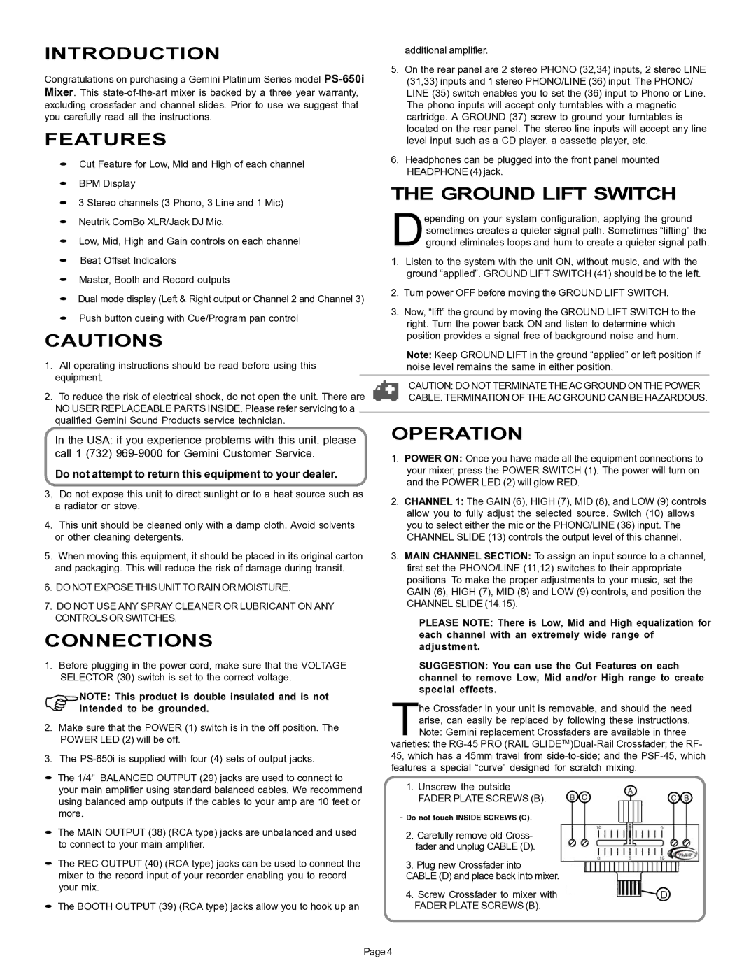
The Crossfader in your unit is removable, and should the need arise, can easily be replaced by following these instructions. Note: Gemini replacement Crossfaders are available in three
varieties: the
1.Unscrew the outside
FADER PLATE SCREWS (B).
- Do not touch INSIDE SCREWS (C).
2. Carefully remove old Cross- fader and unplug CABLE (D).
3. Plug new Crossfader into
CABLE (D) and place back into mixer.
4. Screw Crossfader to mixer with |
| D |
| ||
FADER PLATE SCREWS (B). |
|
|
Page 4