Features
•MOSFET output stage technology for the finest sound quality and reliability
•3 Channel Operation: 2 Satellite Channels (Channels A and B) and 1 Subwoofer Channel
•Full range operation mode for set up without subwoofer(s)
•2-way Linkwitz-Riley crossover with switchable crossover frequency for flexible set up of subwoofer and satellite channels
•Switchable low frequency boost on the subwoofer channel optimizes subwoofer performance
•Stable operation of subwoofer channel down to a 2 Ohm load
•Post crossover line level outputs for chaining additional subwoofers and satellite speakers
•High output power to drive professional loudspeakers without clipping
•Oversized toroidal transformer, filter and heatsinks for better low end, transparency and stability
•Comprehensive protection circuitry (short, overheat, DC, subsonic and RF filters, turn-on delay) with high current speaker protection relays
•True clip LEDs for better control
•Signal ground lift switch eliminates hum from connection loops
•Flexible input configuration with active balanced inputs; additional input connectors to chain amps
•Outputs: 5-way binding posts in 120V; Neutrik Speakon connectors in 230V
•2 parallel 5-way binding posts on the subwoofer output (in 120V only) allows for easy set up with dual subwoofers
•Efficient dual aluminum extrusion heatsink design for thermal stability and reliability
•Front-to-Rear airflow with 2 speed dual fan control
•Turn-on In-rush current limiting circuitry
•Compact 2U well balanced enclosure
•Steel reinforced chassis construction for durability and longevity
Cautions
Read all operating instructions before using this equipment.
To reduce the risk of electrical shock, do not open the unit. There are NO USER REPLACEABLE PARTS INSIDE. Please contact the Gemini Service Department or your authorized dealer to speak to a qualified service technician.
Be sure to allow adequate front and rear ventilation to avoid possible heat damage to your equipment.
Be sure that AC power is OFF and all level controls are set to MINIMUM before making connections. This will eliminate any chance of unexpected, loud audio transients that could damage your speaker systems.
Be sure that AC power is OFF when changing modes of operation and when changing the position of the ground lift switch.
DO NOT EXPOSE THIS UNIT TO RAIN OR MOISTURE. Operators of electronic equipment should in no way be in contact with water.
When connecting to AC power line be sure you haven’t lost the ground connection by using an adapter or extension cord without a 3 prong plug.
DO NOT USE ANY SPRAY CLEANER OR LUBRICANT ON ANY CONTROLS OR SWITCHES.
Input Section:
There are two parallel input connectors (one female XLR and one 1/4” jack) per channel. Either can be used as an input or as a link to chain amplifiers.
XLR Input Jacks (11, 14): electronically balanced inputs accept a standard XLR male connector. Pin 1 = shield/ground, pin 2 = hot or positive (+) and pin 3 = cold or negative (-).
1/4" Input Jacks (12, 13): accept a balanced as well as an unbalanced line level signal. The unbalanced line uses a standard tip-sleeve connection. The tip is positive and the sleeve is negative/ground. The balanced line uses a tip-ring-sleeve connection. Tip = hot or positive (+), ring = cold or negative (-), and sleeve = shield/ground.
Signal Ground Lift Switch (15) is used to lift the balanced input connectors’ ground/shield from the amplifier’s ground. When the signal ground is lifted, the sound source disconnects from the amplifier’s ground preventing ground loops which can generate hum and noise. See the Signal Ground Lift Switch Instructions for more detail.
AC Power Section:
Fuse (7): replace fuse with those of proper type and rating.
AC Cord Outlet (6) is used to attach the power cord to the unit.
Signal Processing Section:
Disconnect the unit from the AC power source before making any connections.
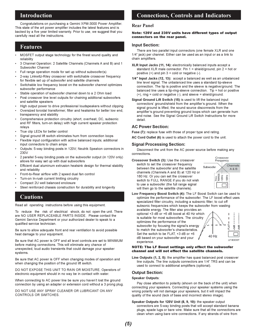
Crossover Switch (3): Use the crossover switch to set the crossover frequency between the subwoofer and the satellite channels (Channels A and B) at 120 Hz or 180 Hz. Or you can set the crossover switch to FULL RANGE if you do not wish to use a subwoofer (the full range signal will then go to the satellite channels).
Low Frequency Boost Switch (4): The LF Boost Switch can be used to optimize the performance of the subwoofer. The LF boost effect uses specialized filter circuitry, including a subsonic filter, to cut off subsonic frequencies which keeps the subwoofer from wasting available energy. The filter also provides an
optional +3 dB or +6 dB boost at 40 Hz which is suitable for most subwoofers. The circuitry optimizes the performance of the subwoofer by focusing the signal’s energy to match the subwoofer’s characteristics. Set the switch to be FLAT, +3 dB or +6
dB based on your subwoofer and your experience.
NOTE: The LF Boost settings only effect the subwoofer channel and will not effect the satellite channels.
Line Outputs (1, 2, 5): the amplifier has quasi balanced post crossover line outputs. The line outputs connectors are 1/4” TRS and can be used to connect to additional amplifiers (optional).
Output Section:
Speaker Outputs:
Pay close attention to polarity (shown on the back of the unit) when connecting your speakers. Connecting your speaker systems using the wrong polarity will not damage your speakers, but it will impact the quality of the sound (lack of bass and incorrect stereo image).
Speaker Outputs for 120V Unit (8, 9, 10): the speaker output connectors are 5-way binding posts that will accept standard banana plugs, spade lugs or bare wire. Make sure that all the connections are clean when using bare wire connections. If any strands of wire from