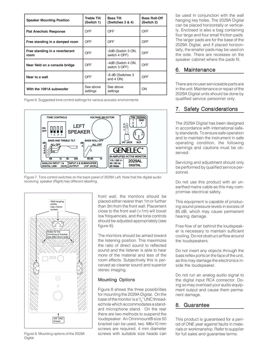
Speaker Mounting Position | Treble Tilt | Bass Tilt | Bass | |
(Switch 1) | (Switches 3 & 4) | (Switch 2) | ||
| ||||
|
|
|
| |
Flat Anechoic Response | OFF | OFF | OFF | |
|
|
|
| |
Free standing in a damped room | OFF | OFF | OFF | |
|
|
|
| |
Free standing in a reverberant | OFF | OFF | ||
room | switch 4 OFF) | |||
|
| |||
|
|
|
| |
Near field on a console bridge | OFF | OFF | ||
switch 3 OFF) | ||||
|
|
| ||
|
|
|
| |
Near to a wall | OFF | OFF | ||
and 4 ON) | ||||
|
|
| ||
|
|
|
| |
With the 1091A subwoofer | See above | See above | ON | |
settings | settings | |||
|
| |||
|
|
|
|
Figure 6. Suggested tone control settings for various acoustic environments
be used in conjunction with the wall hanging key holes. The 2029A Digital can be placed horizontally or vertical- ly. Enclosed is also a bag containing four large and four small friction pads. The larger pads are for the base of the 2029A Digital, and if placed horizon- tally, the smaller pads may be used on the side. There are recesses on the speaker cabinet where the pads fit.
6. Maintenance
There are no user serviceable parts are in the unit. Maintenance or repair of the 2029A Digital units should be done by qualified service personnel only.
Figure 7. Tone control switches on the back panel of 2029A Left. Note that the digital audio receiving speaker (Right) has different labelling.
| front wall, the monitors should be |
| placed either nearer than 1m or further |
| than 3m from the front wall. Placement |
| close to the front wall (<1m) will boost |
| low frequencies, and the tone controls |
| should be adjusted appropriately (see |
| figure 6). |
| The monitors should be aimed toward |
| the listening position. This maximizes |
| the ratio of direct sound to reflected |
| sound and the listener is able to hear |
| more of the material and less of the |
| room effects. Subjectively this is per- |
| ceived as cleaner sound and superior |
| stereo imaging. |
| Mounting Options |
| Figure 8 shows the three possibilities |
| for mounting the 2029A Digital. On the |
| base of the monitor is a 3/8" UNC thread- |
| ed hole which accommodates a stand- |
| ard microphone stand. On the rear |
| there are two methods to suspend the |
| loudspeaker. An Omnimount® size 50 |
| bracket can be used, two M6x10 mm |
| screws are required. 4 mm diameter |
Figure 8. Mounting options of the 2029A | screws with suitable size heads can |
Digital |
|
7. Safety Considerations
The 2029A Digital has been designed in accordance with international safe- ty standards. To ensure safe operation and to maintain the instrument in safe operating condition, the following warnings and cautions must be ob- served:
Servicing and adjustment should only be performed by qualified service per- sonnel.
Do not use this product with an un- earthed mains cable as this may com- promise electrical safety.
This equipment is capable of produc- ing sound pressure levels in excess of 85 dB, which may cause permanent hearing damage.
Free flow of air behind the loudspeak- er is necessary to maintain sufficient cooling. Do not obstruct airflow around the loudspeakers.
Do not insert any objects through the bass reflex ports on the face of the unit, as this may damage the electronics in- side the loudspeaker.
Do not run an analog audio signal to the digital input RCA connector. Do- ing so may overload your audio equip- ment output and cause them perma- nent damage.
8. Guarantee
This product is guaranteed for a peri- od of ONE year against faults in mate- rials or workmanship. Refer to supplier for full sales and guarantee terms.
