Section 8 — Electrical Data

Commercial-Industrial-Residential Portable Generator System

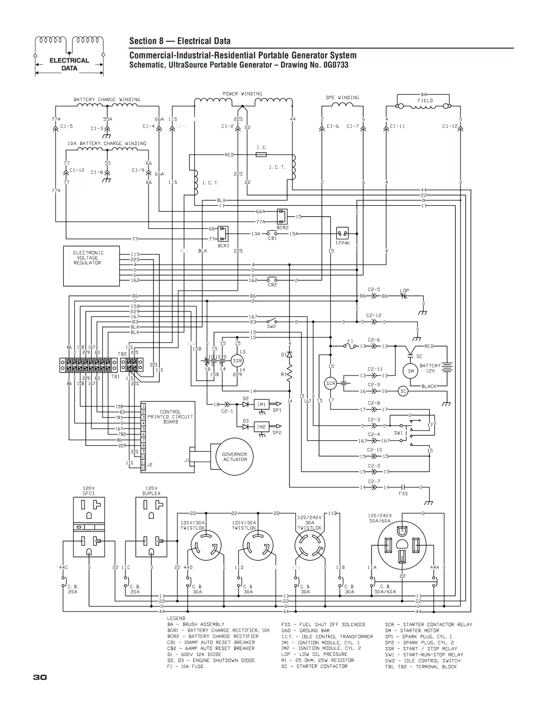
Schematic, UltraSource Portable Generator – Drawing No. 0G0733

BATTERY CHARGE WINDING


POWER WINDING


DPE WINDING


BA


FIELD


77A


55A


66A

11S

11


22S

44


2


6


4


0

C1-5


C1-3


C1-4

C1-1


C1-2

22


C1-6 C1-7


C1-11

C1-12

10A BATTERY CHARGE WINDING


I.C.


RED


77


55


66


I.C.T.


C1-10

C1-8


C1-9


66A


22S


77


66

11S


I.C.T.

22


2


6


4


0

77A


44


22


BLK


0


11


11


66A

15


0


77A


66


BCR2


13A

15A


77


77


CB1


12Vdc


BCR1


BLK


22S


0


4


ELECTRONIC

11S


BLK


15


VOLTAGE


22S


REGULATOR


4


4


0


0


6


6


162


162

2


CB2


C2-5


86


86


86


LOP


86


0


0


0


15B


0


229


C2-12


167


167


0


83


83

0


0


0


BLK


SW2


0


BLK


15


15


F1


C2-6


229

0

15

15

4


13


13


RED

86

15B 167


11S


15B

15


13


0

229

83


TB2 22S


12 10 9

D1


SC


SSR


22S


4 6

5


15


C2-11


BATTERY


11S


18

14

14

R1


SM

12V

0

229

83


TB1 11S


15B

229


13


13


SCR


86

15B 167


22S


C2-9


BLACK


14


16


16

SC


15

0


D2


17


14

167

15


C2-8


15B


18


IM1


1


CONTROL


C2-1


SP1


17


17


83

2


0


TR1

3

PRINTED CIRCUIT


D3


C2-3


0

4

BOARD


17 0


IM2


0


0


167

5


SP2


C2-4

SW1


TR2

6


86

7


167

167


229

8


C2-10


15


22S

9


GOVERNOR


10


15


15


J1


ACTUATOR


11S

11 J2


C2-2


12


15


15


C2-7


120V


120V


14


14


0


GFCI


DUPLEX


FSS


RESET TEST

RESET TEST

22

22

22

11B

120/240V

0


120/240V


50A/60A


120V/30A

120V/30A


30A


TWISTLOK

TWISTLOK


TWISTLOK


44C

0

22 11C

0

22 44D

0

11D

0

44B

0

11B

11A

44A

0

22

C.B.

C.B.

C.B.

C.B.

20A

20A

30A

30A


11


22


0


44


LEGEND


BA - BRUSH ASSEMBLY


BCR1 - BATTERY CHARGE RECTIFIER, 10A


BCR2 - BATTERY CHARGE RECTIFIER


CB1 - 10AMP AUTO RESET BREAKER


CB2 - 6AMP AUTO RESET BREAKER


D1 - 600V 12A DIODE


D2, D3 - ENGINE SHUTDOWN DIODE


F1

- 10A FUSE


30

C.B.C.B.

30A30A

11

22

0

44

FSS - FUEL SHUT OFF SOLENOID GND - GROUND BAR

I.C.T. - IDLE CONTROL TRANSFORMER IM1 - IGNITION MODULE, CYL. 1 IM2 - IGNITION MODULE, CYL. 2

LOP - LOW OIL PRESSURE

R1 - 25 OHM, 25W RESISTOR SC - STARTER CONTACTOR

C.B. 50A/60A

11

22

0

44

SCR - STARTER CONTACTOR RELAY SM - STARTER MOTOR

SP1 - SPARK PLUG, CYL. 1 SP2 - SPARK PLUG, CYL. 2

SSR - START / STOP RELAY SW1 - START-RUN-STOP RELAY SW2 - IDLE CONTROL SWITCH TB1, TB2 - TERMINAL BLOCK

Page 32
Image 32
Generac 004583-0 owner manual Schematic, UltraSource Portable Generator Drawing No G0733

004583-0 specifications

Generac 004583-0 is a powerful and efficient home standby generator designed to provide reliable backup power during outages. This unit is specifically engineered to ensure that homeowners never have to worry about the disruption caused by power loss, keeping essential appliances and systems running smoothly, regardless of external conditions.

At the heart of the Generac 004583-0 is its robust engine, which delivers a peak output of 22 kW and is capable of running on either propane or natural gas. This fuel flexibility makes it an ideal choice for a variety of households, allowing users to select the fuel source that best fits their needs. The generator employs a high-performance, air-cooled engine featuring a durable construction that ensures long-lasting operation, and this reliability translates into peace of mind for homeowners.

One of the standout features of the Generac 004583-0 is its advanced Automatic Transfer Switch (ATS). The ATS seamlessly detects power outages and automatically switches the home’s electrical supply to the generator within seconds. This quick response is crucial for maintaining comfort and safety, especially during extreme weather conditions. The ATS also offers customizable settings, allowing homeowners to prioritize which circuits they want to power during an outage.

In addition to its seamless operation, the Generac 004583-0 integrates innovative technologies such as Mobile Link. This feature enables users to monitor the generator remotely via a smartphone app, providing real-time updates on the system’s status and maintenance needs. This connectivity enhances user experience and simplifies the management of the generator.

The generator is designed with a noise-reduction enclosure, ensuring that it operates quietly without disturbing daily life or neighborhood peace. Furthermore, the unit is built to withstand various weather conditions, featuring corrosion-resistant materials that ensure durability and a long service life.

Safety is paramount, and the Generac 004583-0 incorporates various safety features such as low oil and high-temperature shut-off sensors. These safeguards protect the engine and enhance the overall reliability of the device.

In summary, the Generac 004583-0 is a top-tier standby generator that combines power, efficiency, and advanced technology. With its robust engine, seamless automatic transfer capabilities, remote monitoring, and focus on safety and durability, it stands out as an excellent solution for homeowners seeking reliable backup power.