26 Generac® Power Systems, Inc

2S15

3S16


PCB


4

229


BLUE


SW2


BLUE


1

2

3

4

5


2

3

4

6

7

8

9

10

12

13

15

16

17

6

176


18


BLUE


225A

15


0


23


178


T1


BLUE


162


4


TO GOVERNOR


BLUE

15C

6

4


S16

85


15C

RED

T2

S15


ACTUATOR


178


S16


229


178

239


YELLOW

BLUE

183


BROWN


239


FL

GCU


BLACK


15C

183


176


15C


AS

BLUE


15


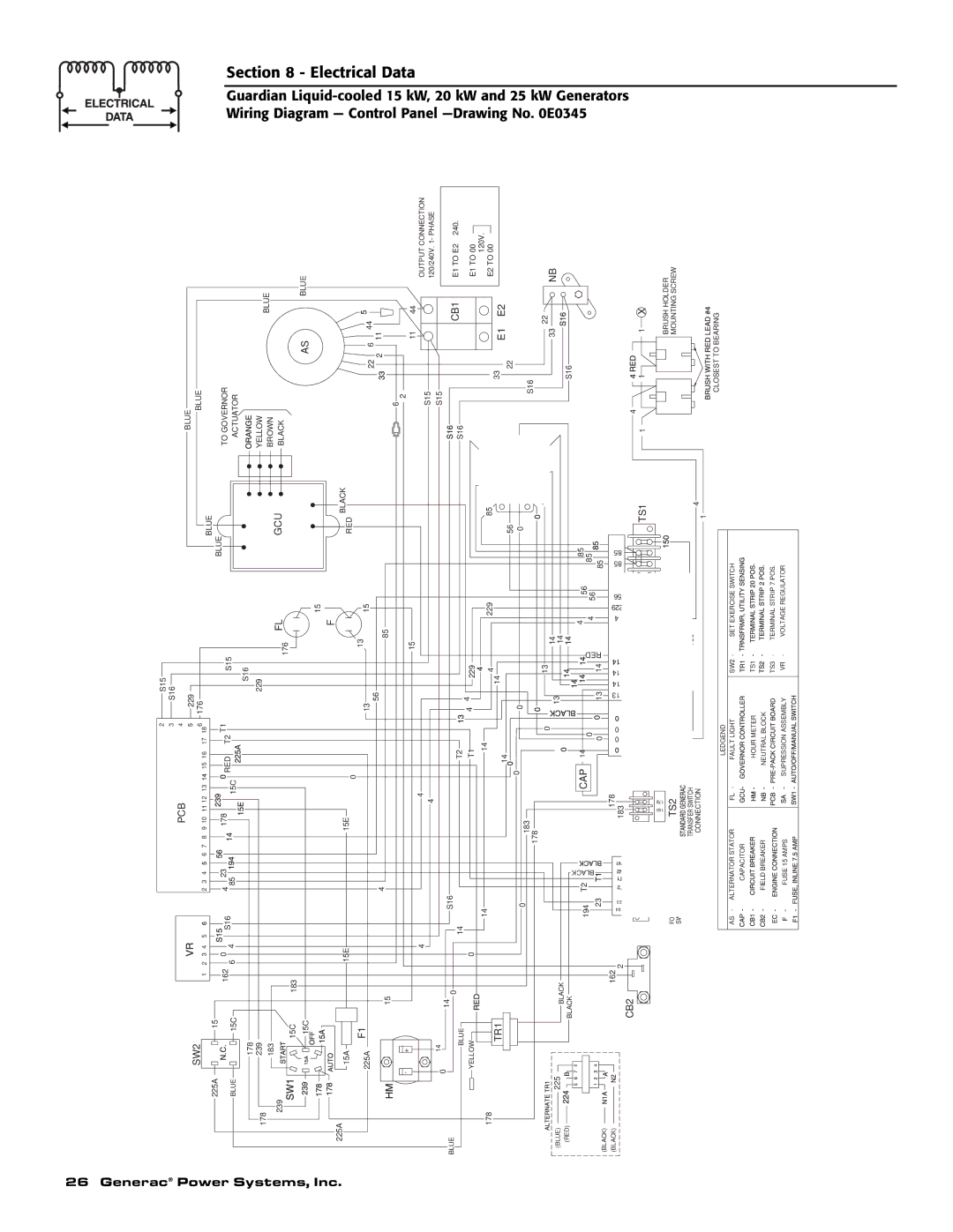
Wiring Diagram

GuardianLiquid

Section 8 -

.

225A

15A


F

15E

15E


BLACK

0

RED


- —

Electrical

225A

F1

13

13

15

4

56

85

15


22

6

44

2


11

6


2


cooled 15 Control

Data

+

0

BLUE

14

BLUE


15

4

4


4

14

S16

0

T2

14

11

44


S15


OUTPUT CONNECTION


120/240V. 1- PHASE

S15


S16

CB1

E1 TO E2 240.


YELLOW

178

TR1

0

T1

4

229


14


14

4

229

85


14


14


33

E1 TO 00

120V.

E2 TO 00

E1 E2

(BLUE)

225

(RED)


8

4

(BLACK)

(BLACK)


0


56


0


0


0


183


178


0


13


14


13


BLACK


14


BLACK


BLACK


194


T2


CAP

14


RED

4


56


85


0


4


85


23


0

13


14


56


85


162

94


178

0

0

13

14

14


4

229

56

85

85

2

23


183


CB2


TS1


183

178


FO


TS2


SW


TRANSFER SWITCH


4


CONNECTION


1


LEDGEND


AS

ALTERNATOR STATOR


FL

FAULT LIGHT


SW2


SET EXERCISE SWITCH


CAPACITOR


HOUR METER


TS1


FIELD BREAKER


NEUTRAL BLOCK


TS3


TERMINAL STRIP 7 POS.


FUSE 15 AMPS


SUPRESSION ASSEMBLY


VR


VOLTAGE REGULATOR


22

S16

22

33 NB


S16


4

1 X

1

1

BRUSH HOLDER

MOUNTING SCREW

CLOSEST TO BEARING

Panel —Drawing

kW, 20 kW and

No. 0E0345

25 kW Generators

Page 28
Image 28
Generac 0047210, 0047220, 0047230, 0047240, 0047250, 0047251, 0047252, 0047253, 0047260 owner manual Section

0047210, 0047220, 0047230, 0047240, 0047250, 0047251, 0047252, 0047253, 0047260 specifications

Generac is renowned for its innovation in the power generation industry, and their range of generators—including models 0047210, 0047220, 0047230, 0047240, 0047250, 0047251, 0047252, 0047253, and 0047260—showcase advanced technologies and functionality that meet diverse power needs.

One of the standout features of these models is the use of Generac’s G-Force Engine, specifically designed for reliability and longevity. This engine is notorious for its durability, capable of handling demanding workloads and proving to be more efficient than typical engines found in similar generators. It provides quick start times, lower emissions, and is built to withstand extended operational cycles.

Another notable technology in these models is the Quiet-Test™ mode, which enables the generator to run at a lower RPM while it performs an exercise routine. This feature not only reduces noise during operation but also conserves fuel, making it an eco-friendly option that doesn’t compromise on performance.

The generators are equipped with advanced monitoring and control features, including the Mobile Link™ application compatibility. This allows users to monitor the status of their generator remotely via a smartphone or tablet, offering peace of mind and real-time access to the generator's operational functioning. This connectivity also enables the user to receive alerts and notifications about maintenance needs or when the generator is in need of attention.

In terms of design, these models boast a robust steel enclosure that offers superior protection against the elements, thereby enhancing durability and ensuring efficient operation regardless of weather conditions. The enclosures also come with a weather-resistant finish, making them suitable for outdoor installation.

Moreover, the generators feature a well-thought-out installation process with easily accessible controls and noise-reduction technology, which helps minimize disturbances for residential applications. They also offer multiple power outputs, catering to varied energy needs, from essential home appliances to larger devices.

Safety is a core consideration with Generac models, and features such as the automatic shutdown mechanism prevent overheating, ensuring operational safety during use. Coupled with an efficient fuel consumption rate, these generators stand out as impeccable solutions for power backup in homes and businesses alike.

The series exemplifies Generac’s commitment to excellence in power solutions, integrating user-friendly technology, efficient performance, and top-tier safety into compact, durable designs. Users can rely on models 0047210 to 0047260 for dependable power generation tailored to their specific needs.