Section 2 – Installation
PRIMEPACT 50 Recreational Vehicle Generator
2.3COOLING AND VENTILATING AIR
It is absolutely essential that an adequate flow of air for cooling, ventilating and engine combustion be supplied to the generator set. Without sufficient air- flow, the engine/generator quickly overheats. Such overheating can cause serious operating difficulties and also may cause fire and personal injury. The installer must make sure that sufficient air is avail- able to the generator for cooling, ventilating and com- bustion. The installer also must provide for a path for exhausting the cooling air to the exterior of a com- partment, if so equipped.
![]()
![]() DANGER
DANGER
Never use discharged cooling air for heating or permit such air to enter the vehicle interior. This air contains deadly carbon monoxide gas and other poisonous, flam- mable or explosive gases.
◆2.3.1 GENERATOR AIRFLOW
Engine operation drives cooling fans for the
Figure 2.9 – Airflow Through Engine/Generator
NOTE:
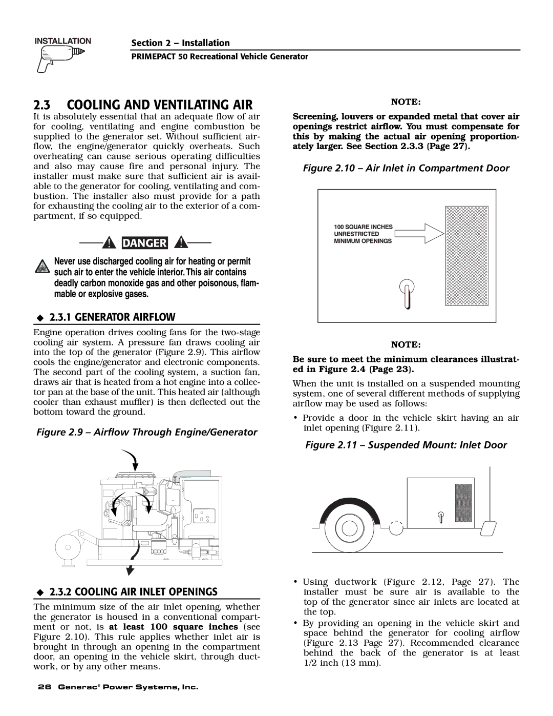
Screening, louvers or expanded metal that cover air openings restrict airflow. You must compensate for this by making the actual air opening proportion- ately larger. See Section 2.3.3 (Page 27).
Figure 2.10 – Air Inlet in Compartment Door
NOTE: |
Be sure to meet the minimum clearances illustrat- ed in Figure 2.4 (Page 23).
When the unit is installed on a suspended mounting system, one of several different methods of supplying airflow may be used as follows:
•Provide a door in the vehicle skirt having an air inlet opening (Figure 2.11).
Figure 2.11 – Suspended Mount: Inlet Door
◆2.3.2 COOLING AIR INLET OPENINGS
The minimum size of the air inlet opening, whether the generator is housed in a conventional compart- ment or not, is at least 100 square inches (see Figure 2.10). This rule applies whether inlet air is brought in through an opening in the compartment door, an opening in the vehicle skirt, through duct- work, or by any other means.
•Using ductwork (Figure 2.12, Page 27). The installer must be sure air is available to the top of the generator since air inlets are located at the top.
•By providing an opening in the vehicle skirt and space behind the generator for cooling airflow (Figure 2.13 Page 27). Recommended clearance behind the back of the generator is at least 1/2 inch (13 mm).
26 Generac® Power Systems, Inc.