GENERAC POWER SYSTEMS, INC. | MPSG350 |
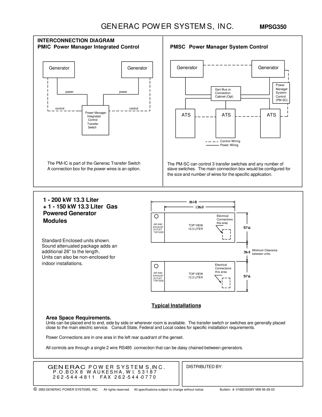
INTERCONNECTION DIAGRAM
PMIC Power Manager Integrated Control
PMSC Power Manager System Control
| Generator |
| Generator | |
|
|
|
|
|
|
|
|
|
|
Generator
Generator
Power
power
control
Power Manager Integrated Control Transfer Switch
power
control
Gen Bus or
Connection
Cabinet (Opt)
|
|
|
|
|
|
|
|
|
|
|
|
|
|
|
|
|
|
|
|
|
|
|
|
|
|
|
|
|
|
|
|
|
|
|
|
|
|
|
|
ATS |
|
|
|
|
|
|
|
|
|
|
|
|
| ATS |
|
|
| ||
|
|
|
|
|
|
|
|
|
|
|
|
|
|
|
|
|
|
|
|
Control Wiring
Power Wiring
Manager
System
Control
ATS
The
The
the size and number of wires for the specific application.
1 - 200 kW 13.3 Liter
+1 - 150 kW 13.3 Liter Gas Powered Generator Modules
Standard Enclosed units shown. Sound attenuated package adds an additional 26" to the length.
Units can also be
|
| Electrical | ||||||
|
| Connections | ||||||
AIR AND | TOP VIEW | this area | ||||||
|
|
|
|
|
|
| ||
EXHAUST |
|
| ||||||
13.3 LITER |
|
|
|
|
|
| ||
OUTLET |
|
|
|
|
|
| ||
TOP SIDE |
|
|
|
|
|
|
|
|
|
|
|
|
|
|
|
| |
|
|
|
|
|
|
|
|
|
|
|
|
|
|
|
|
|
|
|
|
|
|
|
|
|
|
|
|
|
|
|
|
|
|
|
|
Minimum Clearance between units
|
| Electrical | ||||||
|
| Connections | ||||||
AIR AND |
| this area | ||||||
EXHAUST | TOP VIEW |
|
| |||||
13.3 LITER |
|
|
|
|
|
| ||
OUTLET |
|
|
|
|
|
| ||
TOP SIDE |
|
|
|
|
|
|
|
|
|
|
|
|
|
|
|
|
|
|
|
|
|
|
|
|
|
|
|
|
|
|
|
|
|
|
|
|
|
|
|
|
|
|
|
|
Typical Installations
Area Space Requirements.
Units can be placed end to end, side by side or wherever room is available. The transfer switch or switches are generally placed close to the main electric service. Consult State, Federal and Local codes for specific installation requirements.
Power Connections are in one area in the left rear quadrant of the genset.
All controls are through a single 2 wire RS485 connection that can be daisy chained between generators.
GENERAC POWER SYSTEMS,INC.
P.O.BOX 8 WAUKESHA, WI. 53187 262-544-4811 FAX 262-544-0770
DISTRIBUTED BY:
© 2003 GENERAC POWER SYSTEMS, INC. All rights reserved. All specifications subject to change without notice. | Bulletin # 0168230SBY MW |