Section 2 — Installation

40kW Liquid-cooled Generators

2.4BASIC STANDBY ELECTRIC

SYSTEM

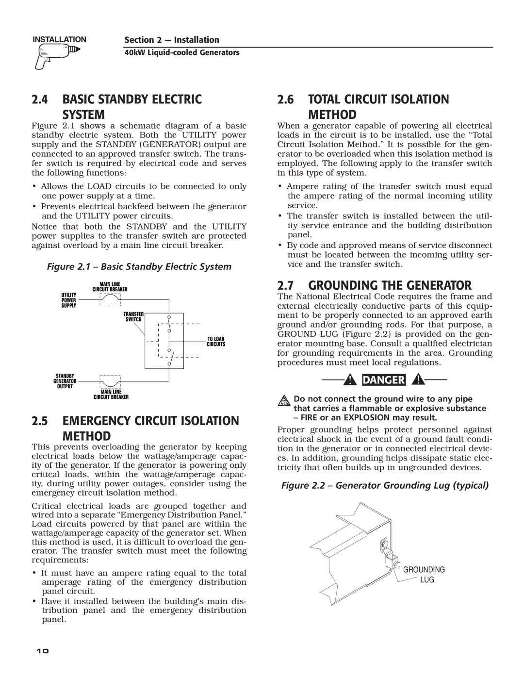
Figure 2.1 shows a schematic diagram of a basic standby electric system. Both the UTILITY power supply and the STANDBY (GENERATOR) output are connected to an approved transfer switch. The trans- fer switch is required by electrical code and serves the following functions:

Allows the LOAD circuits to be connected to only one power supply at a time.

Prevents electrical backfeed between the generator and the UTILITY power circuits.

Notice that both the STANDBY and the UTILITY power supplies to the transfer switch are protected against overload by a main line circuit breaker.

Figure 2.1 – Basic Standby Electric System

2.6TOTAL CIRCUIT ISOLATION

METHOD

When a generator capable of powering all electrical loads in the circuit is to be installed, use the “Total Circuit Isolation Method.” It is possible for the gen- erator to be overloaded when this isolation method is employed. The following apply to the transfer switch in this type of system.

Ampere rating of the transfer switch must equal the ampere rating of the normal incoming utility service.

The transfer switch is installed between the util- ity service entrance and the building distribution panel.

By code and approved means of service disconnect must be located between the incoming utility ser- vice and the transfer switch.

2.5EMERGENCY CIRCUIT ISOLATION

METHOD

This prevents overloading the generator by keeping electrical loads below the wattage/amperage capac- ity of the generator. If the generator is powering only critical loads, within the wattage/amperage capac- ity, during utility power outages, consider using the emergency circuit isolation method.

Critical electrical loads are grouped together and wired into a separate “Emergency Distribution Panel.” Load circuits powered by that panel are within the wattage/amperage capacity of the generator set. When this method is used, it is difficult to overload the gen- erator. The transfer switch must meet the following requirements:

It must have an ampere rating equal to the total amperage rating of the emergency distribution panel circuit.

Have it installed between the building’s main dis- tribution panel and the emergency distribution panel.

2.7GROUNDING THE GENERATOR

The National Electrical Code requires the frame and external electrically conductive parts of this equip- ment to be properly connected to an approved earth ground and/or grounding rods. For that purpose, a GROUND LUG (Figure 2.2) is provided on the gen- erator mounting base. Consult a qualified electrician for grounding requirements in the area. Grounding procedures must meet local regulations.

DANGER

Do not connect the ground wire to any pipe that carries a flammable or explosive substance

– FIRE or an EXPLOSION may result.

Proper grounding helps protect personnel against electrical shock in the event of a ground fault condi- tion in the generator or in connected electrical devic- es. In addition, grounding helps dissipate static elec- tricity that often builds up in ungrounded devices.

Figure 2.2 – Generator Grounding Lug (typical)

GROUNDING

LUG

10

Page 12
Image 12
Generac Power Systems 005012-1 Basic Standby Electric System, Total Circuit Isolation Method, Grounding the Generator

005012-1 specifications

Generac Power Systems 005012-1 is a high-performance generator designed to provide reliable backup power for homes and businesses. Known for its innovative features and advanced technology, this generator is engineered to ensure consistent performance during power outages.

At the heart of the 005012-1 is its robust engine. With a Generac 999cc V-Twin OHV engine, it delivers impressive power output and durability. This engine is designed to run efficiently, making the generator an optimal choice for extended use during outages. The Quiet Test feature allows the generator to run at a lower volume during self-diagnostic tests, ensuring minimal disturbance to its surroundings.

One of the standout features of the 005012-1 is its ability to automatically detect power loss and start up within seconds. This automatic transfer switch ensures that when the primary power source fails, the generator takes over seamlessly, keeping essential appliances and systems operational. This rapid response time is crucial for maintaining comfort and safety during outages.

The generator is equipped with a user-friendly control panel that includes an LCD display. This panel provides real-time information about power usage, operational status, and maintenance reminders, enabling users to stay informed and address any issues promptly. Additionally, the model offers flexible monitoring options through mobile connectivity, allowing users to check the generator's status remotely via smartphone or other devices.

Designed for longevity, the 005012-1 features a durable aluminum enclosure that protects the generator from the elements, ensuring reliable operation in various conditions. Its compact design allows for easy installation and integration into existing power systems without occupying excessive space.

Fuel efficiency is another hallmark of the 005012-1, as it operates on propane or natural gas, providing flexibility in fuel choice. This versatility not only aids in reducing operational costs but also appeals to environmentally conscious users seeking cleaner energy solutions.

Overall, Generac Power Systems 005012-1 stands out as a dependable and technologically advanced generator, combining power, efficiency, and user-friendly features. Its commitment to reliability makes it a top choice for those looking to safeguard their homes and businesses against unexpected power interruptions.