Section 1 — General Information
Guardian
3.Remove the small hose clamp and hose from the fuel regulator. It may be necessary to pry the hose off of the brass fitting using a screw driver to gen- tly lift up the hose edge.
4.Remove the brass hose fitting screwed into the fuel regulator.
5.Locate and identify the brass idle jet. This will be located in the fuel regulator casting facing the front of the unit.
6.Remove the idle jet from its holding location.
7.Place the idle jet, thread side first, into the threaded hole originally occupied by the brass hose fitting.
8.Using a short No. 2 Phillips screw driver, thread the idle jet into the regulator casting. DO NOT OVER TIGHTEN.
9.Apply thread sealant to the threads of the hose fit- ting and replace it into the regulator body.
10.
11.Replace the engine air in baffle using the four M6 screws.
12.Identify both brass adjustment screws on the reg- ulator.
NOTE:
One adjustment screw can be accessed from the front of the unit and the second can be accessed from the back of the unit enclosure by removing the plastic hole plug.
13.To adjust the system to run on LP fuel, turn the adjuster screw that can be accessed from inside the front of the unit, ¼ TURN CLOCKWISE. This should now set the system for maximum power and best performance.
14.It may be necessary to make minor adjustments to the preset adjustment screw settings to achieve maximum power. If experiencing problems with the unit producing maximum power, follow the procedure in Section 2.6 (Adjusting the Fuel Regulator).
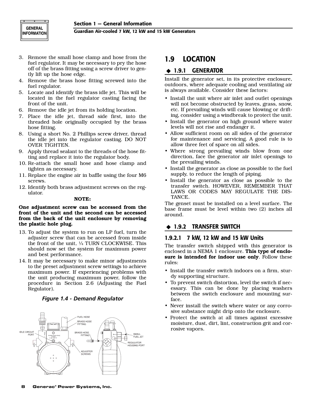
Figure 1.4 - Demand Regulator
1.9LOCATION
◆1.9.1 GENERATOR
Install the generator set, in its protective enclosure, outdoors, where adequate cooling and ventilating air is always available. Consider these factors:
•Install the unit where air inlet and outlet openings will not become obstructed by leaves, grass, snow, etc. If prevailing winds will cause blowing or drift- ing, consider using a windbreak to protect the unit.
•Install the generator on high ground where water levels will not rise and endanger it.
•Allow sufficient room on all sides of the generator for maintenance and servicing. A good rule is to allow three feet of space on all sides.
•Where strong prevailing winds blow from one direction, face the generator air inlet openings to the prevailing winds.
•Install the generator as close as possible to the fuel supply, to reduce the length of piping.
•Install the generator as close as possible to the transfer switch. HOWEVER, REMEMBER THAT LAWS OR CODES MAY REGULATE THE DIS- TANCE.
The genset must be installed on a level surface. The base frame must be level within two (2) inches all around.
◆1.9.2 TRANSFER SWITCH
1.9.2.1 7 kW, 12 kW and 15 kW Units
The transfer switch shipped with this generator is enclosed in a NEMA 1 enclosure. This type of enclo- sure is intended for indoor use only. Follow these rules:
• Install the transfer switch indoors on a firm, stur- |
dy supporting structure. |
• To prevent switch distortion, level the switch if nec- |
essary. This can be done by placing washers |
between the switch enclosure and mounting sur- |
face. |
• Never install the switch where water or any corro- |
sive substance might drip onto the enclosure. |
IDLE CIRCUIT PORT
|
| FUEL HOSE | |
|
| BRASS HOSE | |
|
| FITTING | |
O |
| BRASS HOSE | |
U |
| FITTING | |
T | PRESSURE | ||
1 | |||
TAP |
|
1/8 NPT
ADJUSTER
SCREWS
SMALL
FUEL JET
![]() REGULATOR HOUSING PORT
REGULATOR HOUSING PORT
• Protect the switch at all times against excessive |
moisture, dust, dirt, lint, construction grit and cor- |
rosive vapors. |
8 Generac® Power Systems, Inc.