NOTE
For lightweight garage doors, make sure you have installed the proper reinforcement (See Check Door Condition and Thickness on page 5 in manual),
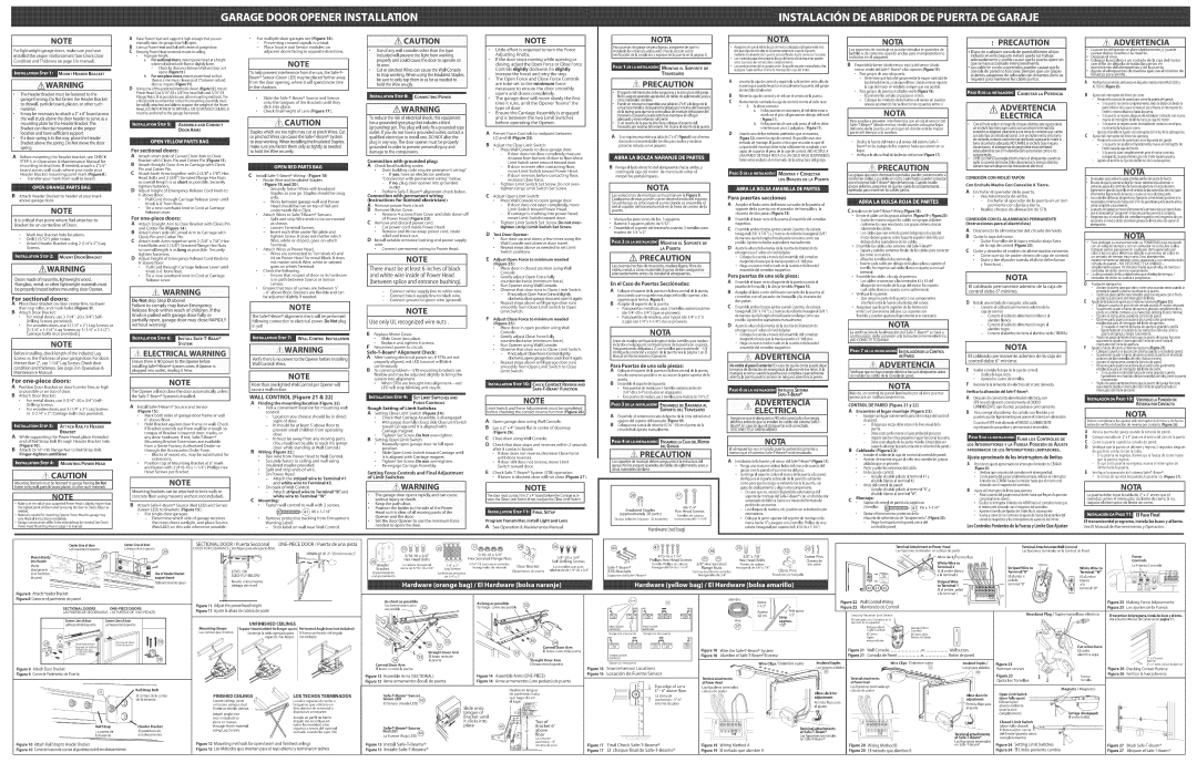
ARaisePowerHeadand support it high enough that you can manually raisethe garagedoor fulmyopen,
BLineup PowerHeadand Railwith center of garagedoor.
CKeepingPowerHeadcentered,mount to ceiming:
At proper height;
a.For sectieea[ deers, mount power headat a height
where rail is levelwith fleer orslightly bwer.
- Checkfor clearancebetween Railand door asit
opens (Figure11).
b, For
For
Preventing crossed signals is critical Place Source and Sensor modules on
adjacent doors facing in opposite directions.
[NOTE
To help prevent interference from the sun, the
CAUT[O
'Use of any wall Consoles other than the type
Jndudedwill preventthe lightfromworking
Little effort is required to turn the Force Adjusting Knobs.
ffthe door stops moving while opening or dosing, adjust the Open Force or Close Force Controls slightly clockwise (to slightly increase the force) and retry the step.
The Open Force and Close Force Controls
[Pare puertasde sara e de peso[igeras,asegOresede que ha | 1 |
Iinstahdo los refuerzosadecuados(VealaNOTA secciBnsobre |
[verificaciBn de lacondiciBny espesorde la puerta en la pagina S)_
_ONTAR EL SOPORTE DE
TRAVESA£O
NOTA
. AsegOresedequeelridde[acaade[motorco[ocadaest_[igeramente_s altoquee[puntom_saltode[acarreram_ximadeviaede[apuerta, mediante[ae[evad6nde[apuertaparaverificado.Ajustecomeseanecesado.
Losmaterialesparae[montajede[acajade[motorde[abrepuertaspueden
variar.Leatodaslasinstrucdonescomp[etamente.
, LasconstrucdonesdelossaraesvarianSepuederequerkmaterialextra..Vea [ap@ina7 parevedficare[_reademontajede[acajade[motoc
|
|
|
|
|
| P | AuTm. |
|
|
| m |
| |
|
|
|
|
|
|
|
|
| ADVERTENC[A | ||||
i | Lossoportes de montaje se pueden instabr | en paredes de | ] | *Elusode cua[quierconsolade pareddiferentea[tipo | o | La puerta | del garaje se abre | r_pidamente, y puede | |||||
ladrilb o de concrete usando andas para mamposteria (no | . | causar dahos | severos o la muerte. | ||||||||||
ieduido | en este paquete | evitar_ que [a Dz trabaje | |||||||||||
induidas | NOTA |
| |||||||||||
| en el paquete). |
|
| adecuadamente y podr[a | causar que la puerta Opere sin |
| Despeje | e[ _rea, |
| ||||
|
|
|
|
|
| Co[oque | la escalera aun costado de [a caja de[ motor" | ||||||
B EnsambHe fuente (diode emisor rojo) y dd sensor(diode |
| que se haya accionado intencionalmente. |
| con e[ fin de alejarla de todas [as partes en | |||||||||
| o Los cable en cordo u opnmidos pueden causar que [a |
|
|
|
|
| |||||||
| emisor verde)del |
| , | movimiento | delabrepuertas | y de la puerta. | |||||||
|
| console | de pared no fuhcione. Siempre que use grapes | ||||||||||
| o Paragarajesde unasob puerta: |
|
|
| Ajuste al abrepuertas de rnanera que use e[ minirno de | ||||||||
|
|
| aisBntes asegOrese de co[ocadas tan distantes come se |
| fufuerza | pare abdrla. |
| ||||||
| - | Determinequ_ bdo dd garajerecibeb mayorcantidadde |
|
|
|
|
| ||||||
| requiera pare mantener os cab esjuntos, |
|
|
|
|
| |||||||
•TheHeaderBracketmustbefastenedto the
mounting plate for the Header Bracket,The Bracketcan then be mounted at the propel
location and have sufficient Support.
If a door spring is in the way place the Header Bracketabove the spring, Do Not move the door spdngi
door asit opens (Figure11 ).
DUsing one of the preferredmethods shown (Figure12}, mount
FlangeNuts).(Itis possibb to useother mounting methods,The critical point to remember is that the mounting assemblymust be solidly attachedand ableto support the weight of the Power Head.)DONOTATTACHTO DRYWALLORSUSPENDEDCEILINGIt. must be anchoredto the garageframework,
ASSEMBLE AND CONNECT
DOOR ARMS
For sectional doors:
Ifromthe door opening,where it will spendmore time in the shadows.
Slide the
Check final height of Lens (Figure 17).
CAUTmON
StapleswhicharetOOtight mayCutorpinchWiresCUt. or
hold the Wire snugly.
] A WA RNmN
To reduce the risk Of e[eEtrical Shock, this equipment
hasagroundedtype plugthat includesathird (grounding)pin.Thisplugwi[[onlyfit a groundedtype
outlet, if you do not have a grounded outlet, contact a qualified electrician to instal[ one. DO NOT aJter the
plug in any way. The door opener must be proper[y
groundedin order to preventpersonalinjuryand
damage to the components.
are tobe set to the mimimum force necessary to ensure the door smoothly opens and closes completely.
The garage door wi[[ move slowly the first time it runs, until the Opener "learns" the type of door.
Ensure the Carriage Assembly is engaged and is between the two Limit Switches
before operating the Opener.
A Pre=set Force Controls to midpoint between
LO and H[ (Figure 25).
BAdjust the CHose Limit Switch:
Press Wall Console to close garage door.
PRECAUTION
'E[ soportede[travesahodebeasegurarseaB estructurade[garaje.
NoIo asegureaparedesagdetadas,detablesde aglomerado,yeso,u otros materMessimilares.
oPuede sernecesadoer.samNarunatabB de 2'x6"a b largode la estructurameteilicade la paredbcalizadaper endmadd travesaho
dela puertaparaquesirvacome platade montajedelsoportedel
travesa_o.E[soportepuedeer.toncesmoetarseen e[ Dgar adecuadoy tenetrefuerzosuficiente.
Siur.rosettede la puertainteffiere,coloqueeBoporte de[ travesa_oper encimadel resorte.Nomuevaelresortede[a puert&
Siserequiere,ensambleunatabh de2"x 6"(Figure8)cona[menos
dos(cuatroesrecomendaNe)tornillosparamaderay rondanas planas(noinduidasconelpaquete).
| Levante[acaja de control y sopBrtda suficientem entealto de | |
| maneraque pueda levantarmanualmente lapuerta delgaraje | |
| abri_ndolatotalmente. | |
B | Alineela cajade control y el rid con el centrede b puerta. | |
C | Manteniendo centradala cajade control, monte al cielo raso: | |
| A laaltura cotrecta: | |
| a. | En_aspuertasen secciones,e[rid debe estara |
|
| nivd con el piso o ligeramentedebajo del nNeL |
|
| (Figura 11). |
| b. | En_aspuertasde una soHapieza,eHrid no debe |
|
| interferir per unas2 pulgadas.(Figure 11). |
Usandouno de los m_todos preferidosque semuestra, (Figure12),monte b cajade control. (Esposibb usarotro re@odede montaje. E[punto crftico que recordaresque el conjunto dd montaje debeestersBlidamenteacopBdo y ser capazde soportar e[ pesode b cajade controL) NOACOPLE
bz dd soldirecta,ycoloqueel foco( diode emisor rojo)de lacajadel motor en _stdado siempreque seaposiNe.
oParegarajesde puertasmO[tip[esvea[a (F[gwa 16):
-Elprevenirlassehalescruzadasescritico.
-Cdoque losmBdulosde b fuente y d sensoren puertas anexasapuntando haciadirecdones opuestasentre sL
NOTA
Paraayudar a prevenir interferencia con el sol, el sensor dd
del vane de la puerta, ee un Dgar ee donde est_ D mayor parte dd tiempo a B sombre.
oDes[iceb fuertte del motor y d sensordd
[ugar.
_L
CONECTAR LA POTENCmA
C[A
,Con elfinde reducirelriesgodechequeel_ctBco,ekeequipotiene unenchufetipotierraquecuentaconunatercerterminal.Esta
conexiBnseadaptar_solamente unatomedecorrientequecuente
_tipodeer.tradaadiciona.Sie enchufer.oentraen atoma
contacteunelectricistacertificado ueleinstalela
A
BAjustede[interrupterde[[[mitede derre:
,Presioneb consdadeparedparecerrarh puertadelsarae.
-Silapuertano derracompletamente,mida[adistanciadesdela parteinferiorde[apuertahastaelpBo.Muevae[interrupterde [Hmitelamismadistandahacialapuerta.
-Si[apuertaseregresadespu_sdeestab[ecercontactocone[piso, muevae[interrupterde[[mitehada[acajade[motet
-Si[apuertaseregresaantesdeestab[ecercontactocone[piso,
klcremente[afuerzadecierre.
C | o | Aprieteeltorni[10defijadBndelinterrupterde[[imiteNo[0sobreapriete | |
Ajustedelinterrupterde/limitede apertura: | |||
| o | Presione[aconsoladeparedparaabrir[apuertade[garae | |
|
| - | 5i[apuertano seabrecomp[etamente,muevae[interrupterde |
|
|
| [imitehacialacajadelmotor. |
|
| - | Si[apuertaabrecomp[etamente,petee[ motorcontinOa |
ABefore mounting the header bracket, see CHECK
STEP4, in Operation & Maintenance Manual for mounting instructions, ff needed, attach a 2"x 6"
board across wall studs where you made your Header Bracket mounting point mark (Figure 8).
Transfer your mark from wall to board.
BAttach Header Bracket to header at your mark above garage door.
NOTE
R is critical that point where Rail attaches to Bracket be on centedine of Door.
Mark two Bracket hole mocations. Drill 2 (5/32") pibt homes.
Attach Header Bracket using 2 (1/4"x 2") Lag Screws.
DOoisrnadeof mas0nite:lightweightWOod, I fiberglass,metN,orother lightweightmaterialsmust
be proper y braced before mount ng door Opener. J
For sectional doors:
A Place Door Bracket on door center line, no lower than top roller, and mark holes (Figure gh
[3 Attach Door Bracket:
For metal doors, use 3 (1/4" =20 x 3/4") Self_ Dri[ming Screws (provided).
For wooden doors, use 3 (1/4" x 2") Lag Screws or _ (1/4" x 1=!/4") Lag Screws or 3 (1/4" x 2=1/2")
arriage boks (not provided).j
A Attach short side of Curved Door Arm to Door Bracket with Clevis Pin and Cotter Pin (Figure 13).
[3 Attach Straight Door Arm to Carriage with Clevis Pin and Cotter Pin.
CAttach both Arms together with 2 (3/'8"x 7/8") Hex Head Bolts and 2 (3/8") Serrated Flange Hex Nuts so overal[ [ength is as short as possible. Securely tighten fasteners.
DAdjust height of Emergency Release Cord Knob to 6'above floor:
Pull Cord through Carriage Release Lever until Knob is 6'from floor.
Tie a new overhand knot in Cord at Carriage Release Lever.
For one-piece doors:
AAttach Straight Arm to Door Bracket with CmevisPin and Cotter Pin (Figure 14).
BAttach short side of Curved Arm to Carriage with Clevis Pin and Cotter Pin.
CAttach both Arms together with 2 (3/8'*x 7/8") Hex Head goffs and 2 (3/8") Serrated Fbnge Hex Nuts so overall length is as ong as possible_ Securemy tighten fasteners.
DAdjust height of Emergency Release Cord Knob to 6'above floor:
Pull Cord through Carriage Release Lever until Knob is 6'from floor.
Tie a new overhand knot in Cord at Carriage Release Lever.
Do Not skip Step D above[
Failure to comply may leave Emergency ReleaseKnob within reach of Children: ff the
Knob is pulled with ga[age door fully or partially open, garage door may dose RAPDLY without wamiDg!
SYSTEM
CInstall
(F_gure lg, and 20).
-Securemyfasten Wires with hsuhted
Stapbs as you go. Stapbs should be snug only.
-Wires between garage wall and Power Head should be run on top of Rail and
underneath Wire Cmips.
Attach Wires to Safe=ToBeam ® Sensors.
-Spmitand strip Wire ends to be connected as shown.
-Loosen Terminal Screws.
-insert each Wire under flat plate and tighten Screw. It does not matter which
Wire, white or striped, goes on which
Terminal,
Attach Wires at Power Head.
-Wires are connected to Terminals #3 and #4 on Power Head Terminal Block. ff does
not matter which WR'e,white or"striped, goes on which Terminal
Check the following.
-Ensure that no part of door or its hardware
is in path between Source or Sensor Lenses.
Ensure that tops of Lenses are between 5"
-6" above floor. Brackets are flexibme and can be adjusted sIightmy if needed.
NOTE
The
in yet[
WALL CONTROL[NSTALLA_ON
Connection with grounded plug: A Checklocal building codes:
Does buimding code require permanent wiring?
ffyes, have an electrician perform "Connection with permanent wiring" below.
ff no, pmugdoor opener into grounded outlet.
. Perform
Connection with permanent wiri#g
(Instructions for [kensed e_ectrician):
A Remove powerfrom circuit. B Remove Motor Cover.
Remove 4 screws from Cover and slide down off
of Power Head (Figure 23). Remove and discard power cord.
Cut power cord inside Power Head. Remove and throw away power cord, strain relief and knock uut.
Dinstall suitable entrance bushing and power supply wire.
Connect permanent wiring to Power Head.
NOTE
There must be at east 5 inches of black and white wire inside of Power Head
(between splice and entrance bushing).
-Connect white supply line to white wire.
-Connect black supply line to black wire.
-Connect ground to green wire (ground).
NOTE
Use only UL recognized wire nuts.
Replace Motor Cover.
Slide Cover into place.
Replace and tighten 4 screws.
- | If door does not dose | completely, | measure | |
| distance | from bottom | of door to floor. Move | |
| Limit Switch same amount toward door. | |||
- | If door | reverses after | contacting | floor, |
| move Limit Switch toward Power Head. | |||
- | If door | reverses before contacting | floor, | |
| increase Close force. |
|
| |
Tighten Limit Switch Set Screw. Do not over= tighten (strip) Limit Switch Set Screw.
CAdjust Open Limit Switch:
Press Wall Console to open garage door.
-ffdoor does not open completely, move Limit Switch toward Power Head.
-ffcarriage is crashing into power head, move Limit Switch toward door.
Tighten Limit Switch Set Screw. Do not over- tighten (strip} Limit Switch Set Screw.
DTest Door Opener:
Run door up and down a few times using the Wall Console and observe door travel
Repeat steps above as needed to set Limit Switch positions.
Adjust Open Force to minimum needed (Figure 2S):
Place door in dosed position using Wail Console.
Gently adjust Open Force fully
counterc[ockwBe (minimum force). Run Opener using VVaHConsole_
Observe that door runs to Open Limit Switch.
-if not, adjust Open Force Control slightly
clockwise, dose garage door, and open it again. Repeat steps above until garage door runs smoothHy from Close Limit Switch to Open Limit Switch.
Adjust Cose Force to minimum needed (Figure 2S):
Place door in open position using Wall Console.
Gently adjust Close Force fully
counterclockwise (minimum force).
BPonga el lade derecho de[ abrepuertas hacia arriba, y sostenga [a caja del motor de manera de evitar el romper los portal_mparas.
Lasvariaciones de montaje se muestran en ia Figure 8. Cuaiquiera de esas puede usarse dependiendo dei espacio.
Sin embargo, es criticoque ei punto donde se ensambia ei rid a_soporte del travesafro est_ en _aiinea de centre de _a
puerta.
•Marque Insposiciones de los 3 agujeros.
•Barrene 3 agujeros pibto de 5/32':
•Ensamble el soporte del travesaho usando 3 torni[Ios para madera de t/4"x 2'.'
_ONTAR EL SOPORTE DE LA PUERTA
PRECAUT[O
as puertas hechas de masonita, madera ligera, fibra de | |
vidno, metal, u otros materia[es ligeros ddSen asegurarse |
|
adecuadamente antes de insta[ar e[ abrepuertas. | J |
En el Case de Puertas Secci6nadas:
ACo[oquee[soporte de [a puerta en [a lineacentral de [apuerta, procurando que no quede masabajode[ rodi[[osuperior,y bs agujerosguia hechos(Rgwa 9).
[} Acopbr el soporte de Hapuerta:
•Para puertas met_[icas, user 3 torni[[os autorroscantes (de 1/4"=20 x 3/4") (que se proveen).
•Para puertas de madera, usar 3 pijas (de 1/4"x 2"6 3 pijas (de 1/4"x 1=1/4") (no se proveen).
[
UNAPAREDDETABLAROCAO A UNCIELORASOSUSPENDDO. Debeestarandado alentramado de b estructura del garaje.
_ONTAR Y CONECTAR
LOS BRAZOE DE LA PUERTA
Pare puertas secdo_es
AAcopBr el lade torte dd braze curvado de D puerta a_ soporte de b puerta con el pasador de horquilb y b chaveta de dos pates (Figure 13).
[} Ensambbel brazerecto de _apuerta alensamNe dd eorredizo magn@ico.
CEnsamNeambos brazesjuntos usando 2 pernosde cabeza hexagonal(3/8 "x 7/8 ") y 2 tuercasde reborde hexagonal(3/8'! de maneraque b Iongitud total quedetan corta come sea posible.Apriete todos lossujetadoresmanualmente_
DAjuste HaaHturade Hamanijade Hacuerdade Hiberaci6nde emergenciaa 6'sobreel nivd dd piso:
. Coloque lacuerdaa travSsdd ensambledd corredizo magn@co hasteque la manijaquede a 6 'dd piso.
. Hagaun nuevo medio nude en lacuerdaen lalevadel ensambledd corredizo magn@co.
Pare p_ertasde ann solepieza:
AEnsembled brazerecto a[ soportede [a puerta usando e[ pasadorde horquilb y ladavija ben@@ (Figure14).
Acop[ar el [ado corto del braze curvado de [a puerta al corredizo con el pasador de horquiIB y la chaveta de dos pates.
CEnsamNeambos brazesjuntos usando 2 pernosde cabeza hexagonal(3/8 "x 7/8 ") y 2 tuercasde reborde hexagonal(3/8 ") de maneraque la Iongitud total quedetan [argacome sea posible Apriete los sujetadoresmanualmente.
DAjuste laaltura de la maniiade lacuerdade liberaciBnde
emergenciaa 6'sobreel nivel dd piso:
"CoHoqueHacuerdaa tra%s dd ensambHedd corredizo magn@co hastaque [a manijaquede a 6 'dd piso.
. Hagaun nuevo medio nude en lacuerdaen b levadd
o Verifiqueb alturafinal de bs bntes del sensor(Figure 17).
CInstalacionde
. Enrutee[ cablecon [asgrapasais[antes(Figwa 19 y Figure 20):
-Sujetede maneraseguralos cablescon grapesaisbntes conformelos vayaenrutando.Lasgrapasdebenabrazar sdamente bs cables.
-Loscablesque vanentre la pared dd garajey b cajadd motor deben guiarsesobre b parte superiordd rid y per debajo de los sujetadoresde los cables.
•EnsamNeloscablesa los sensoresdd
-Separey palebs extremes finalesde los cablespara conectar los come semuestra.
-Afloje los tornillos de lasterminJes.
-Insertecadacableper debajo de lapbca pinnay aprietee[ torni[Io.No importa cualcable,blancoo rayado,va en cual terminal.
,EnsamNeloscanes a la cajade potencia.
-Loscablesseconectan alas terminales#2 y #3dd Noque determinales de lacaja dd motor,No importa cual cable,bBnco o rayado,vaen cual terminal
,Verifique[osiguiente:
-Que ninguna parte de B puerta o suscomponentes interfiereentre lafuente y Dslentes dd sensor.
,Aseg@eseque B pare superiorde Bslentes est_ entre 5 y 6"per encima dd piso.Lossoportesson flexiNes y puedenajustarseligeramentesi esnecesano.
NO CONECTETODAVlA!
siemprequesetrabajeconlasinstalacionesel@tr[caL
CONEXI&N CON _OLmOTAPON
Co_ Enchufe Macho CuR Coeexi6_ A Tierrao
AEnchufar e_ operador de la puerta. Vea Advertencia de arriba.
-Enchufar e_operador de la puerta en un tom acorriente con clavija a tierra.
Realice cheque de alineaci6n de STB.
CONEX[ON CON EL ALA_BRADO PER_ANENTE
{nstruc¢iones pare ememectridsta)
ADesconecte b a_imentad6n de[ drcuito deNvado.
BQuitar B tapa del motor.
Quitar 4 tornilbs de b tapa y resbabr abajo fuera de b caja de control (Figure 23).
CQuite y deseche el cord6n de alimentaci6n existente. Corte cuerda de poder dentro de caja de control Quite y tire e_ poder cuerda, e_alivio del esfuerzo y knockout.
NOTA
Elcableado permanente adentro de la caja de control debe 6" minimo.
InstaHeuna entradade manguito adecuada. ConecteeHcabHeadopermanenteadentro de Ha caja decontrol.
-Conectee[cable dealimentaciBn blanco al aBmbre blanco.
-Conecteelcable dealimentaciBn negro al alambrenegro.
-Conectee[ abmbre de tierra al abmbre verde(TIERRA).
trabaando,muevae[interrupterde[imitehada[apuerta. o Aprietee torni o defijaciBnde imite.Noo sobreapdete.
Serequiempocoesfuerzoparegirar[asperi[lasdeajustedefuerza. Encasedeque[apuertasedejedemovermientrasest_abriendoe cerrando,uBeloscontro[esdefuerzadeaperturaofuerzadederre ligeramentegirandolaperi[[aene[sentidodelasmaned[[asdelrelo (para
incrementar[igeramentelafuerza)yvue[vaaliniciode_stepunto. Loscontro[esaefuerzadeapertureyfuerzadederre@benajustarse[as
necesidadesminimasdefuerzacone[findegarantizarque[apuertaabrey
cierracomp[etaysuavemente
Lapuertade[garae semover[entamente[aprimeravezque@ere,hasta quee[abrepuertas'programe"e[ripedepuertaqueest_acdonando. AsegOresequee[ensam_o[ede[corredizomagn@coest_enganchadoy se
encuentraenmediodelosdosinterruptores8e[[miteantes8eoperare[ abrepuertas
NOTA
Pareproteger sunueva inversion,suPOWERMAXest5equipado con un rolei de tiempo y conun contadorde cidos,[os cua[es
trabajan untos paraprevenircuakNier daho generadoper taler a loscircuitos el_ctricosdebido aun excesode cidos en
un periodo de tiempo muytorte. Sisuabrepuertas repentinamentesedetiene come respuestaa un comando de la consda de pared- NODESCONECTELA UN[DAD-
simplemerlteespere10minutes hasta que e_relo de tiempo / contador de cidos reinicienuevamente.
LadesconexiBnde _aunidad evita que el rebj de tiempo / contador de cidos sevueha a programac
Pruebade[abrepuertas: | . | , , |
,Accione[apuertaparequeabrayderreunascuantasvecesusando[a
consolede paredyobservebcarrerade[apuerta.. | .... |
,_epltalospasosarnDamenclona_osseqOnserequleracone[rmoe
ajusta[[asposicionesdelinterrupterde][mite.
ustedelaruerzaaeaperturaalm[nimonecesario(Figura25}:
Co[oque[apuertaenposkbndecerradausande[aconso[adepaled. Suavementeajuste[afuerzadeaperturagirandocompletamen__ea peril[aen sentldocontrarioalasmanedl[asde[reloj fuerzaminima.
Accioneelab[epuertasusandolaconsoladepared.
Observequelapuertaseaccionaoeacuerdoa lospar_metros
estab[edoosparqe[interrupterde[[[mitedeapertura. , ,,
-SinoajusteelcontroldefuerzadeaperturaqirandoR peril[a
[ geramenteene[sentdo delasmanec[[asde[re[oj,derre[a R puertade[garaje,y_bra[anuevamente_ , ....
epdalospesosantenoresnastaquelapuertade garaprunaone suavementedes@e[ interruptoroe[[imitedecierrehastae[
Before installing, check length of the induded Lag Screwsvs. the thickness of your garage door. For doors thinner than 2", use 1ol/4" Lag Screws.Check door
condition and thickness. Seepage 3 in Operation & Maintenance Manual
For one-piece doors:
APosition Door Bracket on door'scenter line, as high as possible or on top of door.
BAttach Door Bracket:
For metal doors, use 3 (1/4" =20 x 3/4'*)Serf=
DNlling Screws.
For wooden doors, use 3 (1/4" x 2") Lag Screws or 3 (1/4" x 2")Carriage hefts (not provided).
ELECTRICAL WARNING-
Ensure there is NO power to the Opener before
installing
NOTE
The Opener will not dose the door automatically unless
the
A [nsta[I Safe=T=Beam ® Source and Sensor |
(Figure1 S): |
[_ wAR.m.G
More than one lighted Wall Central per Opener will causea maffunEtion.
WALL CONTROL (Figure 21 & 22)
A Finding the mounting location(Figure 22).
Pick a convenient location for mounting wail control
F Reconnect power to circuit.
After turning electrical power on, if STBs are not properly aligned, red LED (source) will b_ink continuously.
B To correct
When STBs are brought into
FORCE CONTROLS
Rough Setting of Limit Switches
A Setting Close Limit Switch (Pigure 24):
Run Opener using Wall Console.
Observe that door runs to Cbse Limit Switch.
-If not, a_ust Close Force Control slightly clockwise, open garage door, and close it again.
Repeat steps above until garage door runs smoothly from Open Limit Switch to Close Limit Switch,
SAFE-T-BEA_ ® FUNCTmON
[
Limit Switch and Force Adjustments must be completed before checking the contact reverse function F sure 25).
induidos en el paquete contrad espesor de la puerta de su garaie, Para puertasm_s ddgadas a 2'; use tornillos para madera de
Manualde Mantenimientoy Operaci6n.
Pare Puertas de ann sole plezas:
AColoque elsoporte de b puerta en la [ineacentral de B puerta, tan alto come seaposiNe o en sucaseen b parte superiorde b puerta.
BEnsamNeel soporte de b puerta:
•Parepuertas de metal use3 torni[[os autoroscarttesde
,Parapuertasdemadera,use3tornillosparamaderadel/4"x2't
SOPORTE DEL TRAVESANO
ensamNedd corredizo mash@ice.
_ede | @jar [ |
[_os.Si | b [ |
| INSTALEELSISTEMA |
|
[NSTALAC_0NDELACONTROL DEPARE#
ZL ADVERTENC A
Verifiqueque no hayaenergiael@trica haciael abrepuertasantes |
|
de insta[ar loscanes de [aconsole de pared. | J |
NOTA
M_s de un control de pared iDminado per e_abre puertas )rovocar5 un maffuncionamiento_
CONTROL DE PARED (Figura 21 y 22)
A | Encontrar | el [ugar montaje | (Figura 22): |
NOTA
Elcableado permanente adentro de la caja de CONtroldebe 6" minimo.
EVudva a instaBr [atapa de [a cajade contrd. DesHice[atapa, recto.
Apriete loscuatro (4)tomilbs.
FReconectelaalimentaciBn el_ctricaalcircuito derivado.
Verificar _aa[i_eadB_de[Safe-T-Beam®:
A | Despu_sde conectar Haa[imentaci6n d_ctrica, s[d |
| STBno est_alineado correctamente,e[ DIODO |
| LUMNSCENTErojo (fuente) parpadear_continuamente. |
B | Paracorregir e[ proNema- bs cartdas sonf[exiNesy se |
interrupterde[[imitede aperture. ustelatuerzadecJerreaimmJmonecesario.(Figura25):
Coloque[apuertaen[aposidBnabiertausan[Jolacons@depard,
Suavemen!eajuste[afu?rzadecierregirandolaperi[[aene[sentido contradooe[asmaneci,asuelreloj(fuerzaminima). Accionee[ab,repuertasusando[acons@d,epareu. ObservequeRpuertaseacdonadeacuerdoa lospar_metros estab[eddosparae[interrupterde[[[mitedederre
-Sino a ustee[controldefuerzadecierregirando[aperi[[a
geramenteene sentdode[asmaned[[asde[ e[oj,c e apueta nuevamente.
Repitalospesosantedoreshastaq.u.elapue[tadelgarajefuncigne
suavementedes@e[interruptordellimitedeaperturahastael interrupterde[I/mitede cierre.
VER_FmQUELAFUNOON DE
REVERSAPORCONTACT{:)
f
ATTACH RAL TO HEADER [}RACKET
Mark both sides of garage door frame or waHH |
6" above floor. |
Hold Bracket against door frame or wall Check |
if Bracket extends out from wall far enough so |
tongue of Bracket is beyond door, tracks, or |
- | Location | you choose | should be in direct |
| sight of | door. |
|
- | h should | be at least | S'above floor to |
| prevent small children from operating | ||
| door. |
|
|
Check that Carriage Assembly is disengaged. With garage door fully closed, slide Close Limit Switch toward Carriage ueq it is aligned with
Carriage magnet.
A Open garage door using Wall Console.
Lay a 2" x 4" board flat in center of doorway (Figure 26).
AEnsambHeeHextreme roscadodellperno de Hacinta dd rid en eH agujerode[ soporte de[ travesaflo(Figure 10).
Coloqueuna tuercade reborde
Escogerun Dgar conveniente para el montaje dd control |
de pared. |
Elbgar queescojadebeestarenb linenvisualdeb |
puerta. |
Debeestarper Io menosa5 piesarribadelpisopara |
pueden ajustarligeramente para poner e[ sistemaen alineaciBn. |
Cuandoe[ STBest_ alineadoel DIODOLUMINBCENTE |
rojo dejar_de parpadeary permanecer_encendido. |
m
A Abra [a puerta de[ garaje usando[a conso[ade pared. |
AWhile supporting the Power Head, place threaded end of Rail Strap Bolt through Header Bracket hole (Figure lg).
BAttach (S/16"=18) FDnge Nut to Rail Strap Bolt.
Finger=tighten unti ater.
MOUNT'NOPowERHEA
Z UTnO
ounting Bracketsmust befastenedto garaqefram!ng,De Ngt 1 fastento drywall, particleboard,plaster,or orbet suct_rhateriak
. Makesurethe railof yoursupportedPowerHeadisslightlyhigherthan
thehighestpointof doortravelbyraisingthedoorto check.Adjustas needed,
,MaterialsneededformountingOpenerPowerHeadto garagemay vary.Readall instructionscompletely.
. Garageconstructionsdiffer.Extramaterialmaybeneeded,SeeCheck PowerHeadMountingAreaonpage7 in manual
any door hardware. Hfnot, Safe=T=Beam ® | |
Mounting Bracket Extensions are avaimabme | |
from a Genie Factory Authorized Dealer or | |
through the Accessories Order Form_ | |
- | Bmocksof wood, etc. may be substituted for |
| extensions. |
Position top of Mounting Bracket at 6" mark and fasten with 2 (#10=! 6 x 1=1/4") Phillips Hex Head Screws per Bracket.
NOTE
Mounting Brackets can be attached to brick walls or concrete floor using masonry anchors (not included).
BAttach
For
-Determine which side of garage receives the most direct sunlight, and place Source (Red LED) on this side whenever possible.
- | It must be away from any moving parts. |
| (You should not be able to reach the garage |
| door while standing at Wall ControL) |
[} Wiring (Figure 22):
Run wire from Power Head to Wall Control.
Securemy fasten to ceiling and wall using insulated staples provided.
SpHit and strip ends of wire. On Power Head:
-Attach the striped wire to Terminal #1 and white wire to Terminal #2.
On back of Wa[I Control:
-Attach striped wire to Termlna"B'[and white wire to Term[naJ "W':
CMounting:
Fasten wail control to wail with 2 screws.
_ | _ | #6 x 1=1/4" |
Remove protective backing from Entrapment Warning Label
-Stick bbem on wall near Wall Control
Tighten Set Screw. Do Not over=tighten. Setting Open Limit Switch:
Manually open garage door to full open position.
Slide Open Limit Switch toward Carriage unti_ it is aligned with Carriage magnet.
Tighten Set Screw. Do not over=tighten. Re=engage Carriage Assembly.
Setting Force Controls e_d Final Adjustment of Limit Switches
m
•Thegarage dooropens rapidly, and Can pause
sedous injury or death.
,Keep the path dear.
. Position the ladder to the side of the Power Head so it is clear of all moving parts of the Opener and the door.
-Set the door Opener to use the m!n!mum force needed to open the door.
CCHosedoor using Wa[_Console.
DCheck that door stops and reverses within 2 seconds after it contacts board:
o If door does not reverse, decrease Close Force untiH door reverses.
,ff door still does not reverse, move Limit Switch toward door.
ECheck Safe=ToBeam ® System (STB) operation:
• ff beam is blocked, door will not dose (Figure 27).
NOTE
The door mustcontact the 2"x 4" board beforethe Carriageacti- vatesthe CloseLimit Switch.If not,readjustthe dose Limit Switch.
Program Transmitter, install Light and Lens
A See Operation & Maintenance Manual.
ENSA_4BLELACAJA BEL MOTOR [)ELGARAJE
PRECAUTION | ] |
Lossoportede moRtajedeber,asegurarselaestructuradel |
|
garaje,No los asegureaparedes,de taNas de aglomerado,yeso,u | J |
otros materiaes slmi ares |
insulated | Staples | #6=11/4" | |
Pan Head Screws | |||
(approximately | 30 | parts) | TorniI[os de cabeza |
|
|
| |
Grapes aisbntes (Approx | 30 inidades) | troncocBnica#6 = ] =1/4" | |
Hardware(red bag)
EHabrepuertas no cerrarg [apuerta autom_ticamente a menos que el sistema Safe=T=Beam® est_ instabdo.
InstaBd6n de B fuente y e[
•Pongaunamarcaen ambos _adosdd marcode puerta del garajeo en la pared a 6"per encimadel piSOa
°Sostengael soportecontra el marcode la puerta o la pared. Verifiquesi el soportesobresalede la pared Io suficiente come paraque la espigaseextiendahacia lapuerta,sus guiasde deslizamientoo algOnotro componente.
-Encaseque no, existendisponibles extensionesde[ soportede montaje del
-Losbbques de madera etc puedenser substituidos per extensiones.
oCo[oquela parte superiordd soporte de montaie en B marcahecha 6"y asegurecon 2 tornillos Phillipsde cruz cabezahexagonalper soporte dd(
impedirquelosnihospequehoshaganfuncionar[apuerta. |
Debeestarabjado delaspartesm6v@s(Usteddebeset capazdeakanzarB puertaestandoen e[controldepared.)
B Cab[eado (Figure22):
Instabr el cane de b cajade controlal controlde pared. Apretar de manera seguraaHcido raso usando Hasgrapes aisladasque seproveen.
Partu y pelar los extremes del cable. Enla cajade control:
-Acoplar e[ cable pdado altermmal #I y e[ cane blaneo al terminal #2
Atr_sdel control de pared:
-Acoplar e[ cable pdado alterm!nal '3",y e[ cane blanco al terminal "W".
CMontaje:
Sujetare[ control de pared a la pared con
2 torni,,os _}_@#6x1=1/4" Quitar e[forro interne protector de [a
etiqueta de advertencia de "atrapamiento".(Figura 23).
-PegarB etiqueta en lapared,cerca dd control de pared
FUAR LOS CONTROLE$ DE
LOS [NTERRUPTORES Y LA FUERZA PosmcmoN DE AJUSTE
APRO×m_AOO DE LOS _NTERRUPTORESLm_TADORES.
Aj_steaproximadode los intetrruptorsde m_mitBs
APosiciBndeajusteaproximadode[interrupter[irrfitadordeCERRAR
(Figure24),
'Verificarqueconjuntodelcorredizoest_desenganchad. Conlapuertade[garajetotalmentecerrada,resba[are[interrupter [imitadordeCERRARhadae[corredizohastequee[mismoest_ a[ineadocone[magnetode[corredize
BA ustede[interrupterdelimitepareapertura:
o Abraapuertade garajemanuamentehastaque eguea a posiciBn comp[etamenteabierta.
,Deslizere[intrruptorlimitadorde ABR[Rhadae[corredizohasteque e[mismoest_a[ineadoconelmagnetode[corrediz&
•Aprieteeltorni[[odefi aciBnde[IfmiteNo[osobreapriete. Vue[va conectarloscontro[esdeajustedefuerzade[ensamb[ede[ corredizomagn@coylosinterruptoresdeajustedelos[{mites.
LosCoRtremesPo ieRtesdemaFuerzay UmiteQ_eAjustan
B | C0[0queunatablade 2"x 4"pinnaenel centrede[clarede [apuerta. | |
C | Cierre [a puerta usando[a console de pared. | |
D | Verifiqueque [a puerta sedetiene y regresa2 segundosdespu_s | |
| de que Nzo contacto con la tabla. | |
| o | Si[a puerta no regresa,disminuya [afuerza de cierre hasta |
|
| que [a puerta regrese |
| • | Siaun asi [a puerta no regresa,muevae[ interrupter de |
|
| hmite hacia la puerta. |
Vedfique [a operadBn de[ sistema
° Sie[ hazde [uz est_ b[oqueado,[a puerta no. (Figura 27),
NOTA
La puerta debe tocar Hatab[a de 2" x 4" antes que el corredizo active el interrupter de limite de derre. Si no, reajuste e[ interrupter de _imite de cierre.
ElPasoFinal
El tra_smisorde[ programa, i_sta[a [as [uzes y el lento.
Vea El Manual de Mantenimiento y Operaci6n.
CenterLineaf doer | CenterLiceof door |
La[Rleacentrald epuerta | Lalineacentrald epuerta |
', |
|
o0a0,dir.0tl;! - __ |
|
intoHeader |
|
SECTIONALDOOR/ Puerta Seccional ONE=PiECEDOOR/ Puerta de una p[eza
CHECKEORCLEARANCE/ VeBfiquepara e_espacio[ibre.
MNMU/I OF2"/E[ minimo de 2"
®???
5/!6=18 x 3/4" | 5/16=18 x 3/4" | 1/4"=20 x 3/4" | |
Hex Head Bolts | Hex Serrated FHangeNuts | ||
Self=Drilling Screws | |||
|
|
#10=16 x 1V4" Phillips Hex Head Screws
3/8" x 7/8" | _. | Cotter Pins |
TerminalAttachment at PowerHead | Termieal Attachmeetat | Wall Control |
LasRjaciBnesterminales en cabezade poder | Lasfijaci6nes termina[es | en [a Central |
Mbw sDck/Permita r_ojo |
|
|
de Pared
Force
Contro[e
| Monte |
|
|
|
| |
| directamente.:S2 | _ | derBracket | |||
| "__' | ._:::e:_. | ||||
| depared | _____ |
| " | .::_= | oard |
|
|
|
|
|
| Tableadicionaldeapoyo |
Figure 8 | Attach | Header Bracket |
|
|
| |
Figure 8 | Conecte e[ par_ntesis de pared |
|
| |||
|
|
| SECTmONAL | DOORS | ||
H SLIGHTLYBELOW
Figure 11 Adjust the power head height
Header | La cabeza hexagonal | 1/4"x | 2" | 5/16"=18 Las nueces | serradas | Door | Bracket |
|
|
| |
hexagona_es de | reborde | Los torni[[os | que | auto | |||||||
Bracket | cierra de 5/16"=18 x 3/4" | Lag Screws |
|
| |||||||
|
|
|
| ta_a@ando de | x 3/4" | ||||||
E[parantesis de |
| La demora encrosca |
|
| E[par_ntesis de puerta | ||||||
|
|
|
|
|
| ||||||
encapezamiento |
| de 1/4"x | 2" |
|
|
|
|
|
|
| |
As short as poaaibme |
| Aa ioegaa poasibie | |
Tan brevemente come | /*_, | ||
Tanlargo como seaposible | |||
|
|
Torni_[o | Phillips de cabeza | 3/8" Hex Serrated | HexPernosHeadde cabezaBobs | _ | Chavetados patesde | ||
hexagonal | Flange | Nuts | hexagona_ de 3/8"x | 7/8" |
| ||
(STB) Brackets |
|
| Tuercas de reborde serradas |
| Clevis Pins | ||
|
|
|
|
| |||
Supportes de_ | @ |
| hexagona_es | de 3/8" |
| Pasadores | de horqui[[a |
aHambra | |
..... | Aprox. [ H |
White Wire to |
|
| TERMINALS | ||
Termioam2 |
|
|
| ||
|
|
|
| ||
E"a[ ambre b,anco l\\\/11 | Te_mina_"B" | ||||
a,oterm,n2%. | Elal ambr e | ||||
pelado |
| ||||
Etriped Wire | %, |
| |||
terminal | "B" | ||||
|
|
| |||
Elalambre | pdad | t _ | Striped | Wire t<_ | |
a [a terminal 1 |
| ||||
toTermina[ | 1 | _'_j |
|
| |
Figure 22 Wail Control WMng
Figure 22 A[ambrado de Control
La Fuerza Contro[a
White Wire to
Terminei "W"
Elal ambre blanco
a[a terminal "W"
Figure 25 Making Force Adjustments
F_gura 25 Los ajustes de _aFuerza
LASPUERTASDE SECC[ONADAS LAS PUERTASDE UNO PEDAZO | |
CenterL_neaf doer | Ceeter L_neafdeor |
La[[neacentrald epuerta | La[ineacentra[depuerta |
Figura 11 Ajuste [a a[tura de cabeza de poder
UNFiNiSHED CEiLiNGS
sea )osibHe_m, qR3k-_)
| A | r x | _< Peb_prox |
"_ | , | i ,/J//Rrip | |
Wire |
| /// | approx. |
@ |
| j | 1 2'" |
|
| ||
Security Vacation Lock Switch | Knockout pmug/Tap6nmaraviRoso | el_ctrico | lento. |
| E_transmiser de[ programa,insta[a _as[oaesy el | ||
|
| Veaa Du@o's/Manua[de Conservaci6npagiea 11. |
|
Mounting | Straps | supportbeardaddedformo.gerspa_s Perforated Aegme[ren/not in_muded) | |
Las xorreas | que montan | Sostengalatabla agregadapare | El hierro perforado del angulo |
|
| espaciosrn_slargos | (no induy6) |
It_1 /_ | "'L _StraightDoorArm |
_'(g_h Elbrazo recto de |
El braze curve de la puerta
Garaje con u_a puerta | Garaje con dos puerra |
Figure | 18 | Wire the |
|
|
| |
Figure | 18 | A[ambre | el | Figure21 ConsoB de Pared | o | Bot6n de pared. |
Cut w_res here.
El corte
alambra aqui.
(3_z | ":_' lapuerta |
Curved Door Arm
\ 5@lraight Door Arm El braze recto b puerta
Gara N con tres puerta
Wire cmips/Ela[ambre sujeta | mnsalatedStaples | Wire C[ipe Ela[ambre sujeta | insulatedStaRlet/ Figure 23 |
|
| @ |
|
2" x 4" board [aid flat
2"x 4"table co[oc6 [a p[anicie
Figure 9 Attach DoorBracket
Figure 9 ConecteParBntesisde Puerta
Rei[ Strap |
|
La correa de | Elpar6ntesis de |
la baranda | encabezamiente |
|
Figure 10 AttachRailStrapto HeaderBracket
Figure 10 Conectebarandacorreaa[ par_ntesisde[encabezamiento
FNSHED | CELNG$ | LOS TECHOS TERM_NADOS | |
Locate ceiling | joists | Locabceviguetas de techo o | |
ortrusses using a stud | braguerosque utilizana un | ||
finder or similar device. | descubridor de semenralo | ||
Attach angle iron | disposaivo semejante. | ||
Acople un perEI de hierro | |||
(net included) te | |||
joists or trusses | _ngulo (no se incluye en | ||
redes los mode[os)alas | |||
through finish material | |||
viguetas a trav#s del mateRa[ | |||
|
| ||
using Lag Screws | acabado usando [aspijas(30). |
|
Figure 12 Mounting methods for open beam and finished ceilings
Figura 12 Los MBtodos que montan para el rayo abierto y terminaron techos
Elbrazecurvode Hapuerta
Figure13 Assemble Arms (SECTIONAL) Figure13 Arme armamentos (local) de puerta
Green LED | @ |
ElSensor (Verde LED) |
|
_
Red LED
La Fuente (Roio LED)
Figure 1S install Safe=T=Beams ® Figure 15 [nsta[e Safe-T-Beams ®
Figure 14 Assemble Arms (ONE=P_ECE)
Figure 14 Arme armamentos (uno pedazo) de puerta
| Deslice en lengua |
|
| |||
| de par_ntesis hasta |
|
| |||
| que haga dic | en |
|
| ||
| el lugar | __ |
|
|
| |
tongue | of |
|
|
|
|
|
Bracket | until |
|
|
|
|
|
lide onto |
|
|
|
|
| |
it dicks | into |
|
|
|
|
|
place | // | / I":: [ | B:racket | 6" | ||
| ' _ (47_ | I | .above | |||
| Topof | |||||
|
|
|
| floor |
|
|
| ,_ | _ | ." _ | La alma | de |
|
| ._ | , H | .'[' |
| ||
|
| enc,ma | de | piso | ||
| IIIlfi_!t#_ljI,LLL_ |
|
| |||
Figurer5 Source!sensor Locations
Figure16 Locaci6n de Fuente/Sensor
5" = 6" above fbor
La cima de
Top edge of Lens par_ntesis
endma de piso
Figure 17 Final Check Safe-T-Beams ®
Figura 17 El cheque final de Safe=T=Beams ®
|
|
|
| Losgrapesaisladas | Remove | screws |
|
| ||
|
| Te_miea attachments |
| Figure | 23 |
| _ | I | ||
|
|
| Quita | bs | TorniHos |
| _, | |||
|
| at PawerHead |
|
| ||||||
|
|
|
|
|
|
|
|
| ||
|
| Lasfijacidnes | terminales en |
|
|
|
|
|
|
|
|
| cabeza de poder |
|
|
|
|
|
|
| |
|
|
|
| Aliew sleekfor | Open | Limit Switch |
|
| ||
|
|
|
| _djustmeRt | (deer | felly | open) |
|
| |
|
|
|
| E[ Interrupter |
|
| ||||
|
|
|
| Rojopare |
|
| ||||
|
|
|
| abierto | dd | I[mite |
|
| ||
|
|
|
| el ajuste |
|
| ||||
|
|
|
| (puerta | abre |
|
| |||
|
|
|
|
|
|
| ||||
|
|
|
|
| completament) |
|
| |||
|
|
|
|
| ClosedLimit Switch |
| ||||
| ! | Termieai attachments |
|
| (door fury dosed) | _[_[ .... |
| |||
|
|
|
|
| ||||||
|
| at |
| Terminal attachments | EHInterruptor cerrar |
| ||||
|
|
| de[ [[mite | (puerta | cerrd |
| ||||
|
| Lasfijacidnes terminales |
|
| ||||||
|
|
| at |
|
|
|
|
|
| |
|
| en |
| comp_etamente) |
|
| ||||
| F |
| Lasfijaddnes termina[es |
|
| |||||
|
|
|
|
|
|
|
|
| ||
Figure 19 | Wiring Method A | Figure 20 Wiring Method B | en | Figure24 |
| Settin 9 Limit Switches | ||||
|
| |||||||||
Figure lg | E[ re@ado que a[ambre A | Figure 20 | E[m_tado que a[ambre B |
| Figura | 24 | El L{mite | poniente | cambia | |
Screw
Tornillo
Elcoche (salt6)