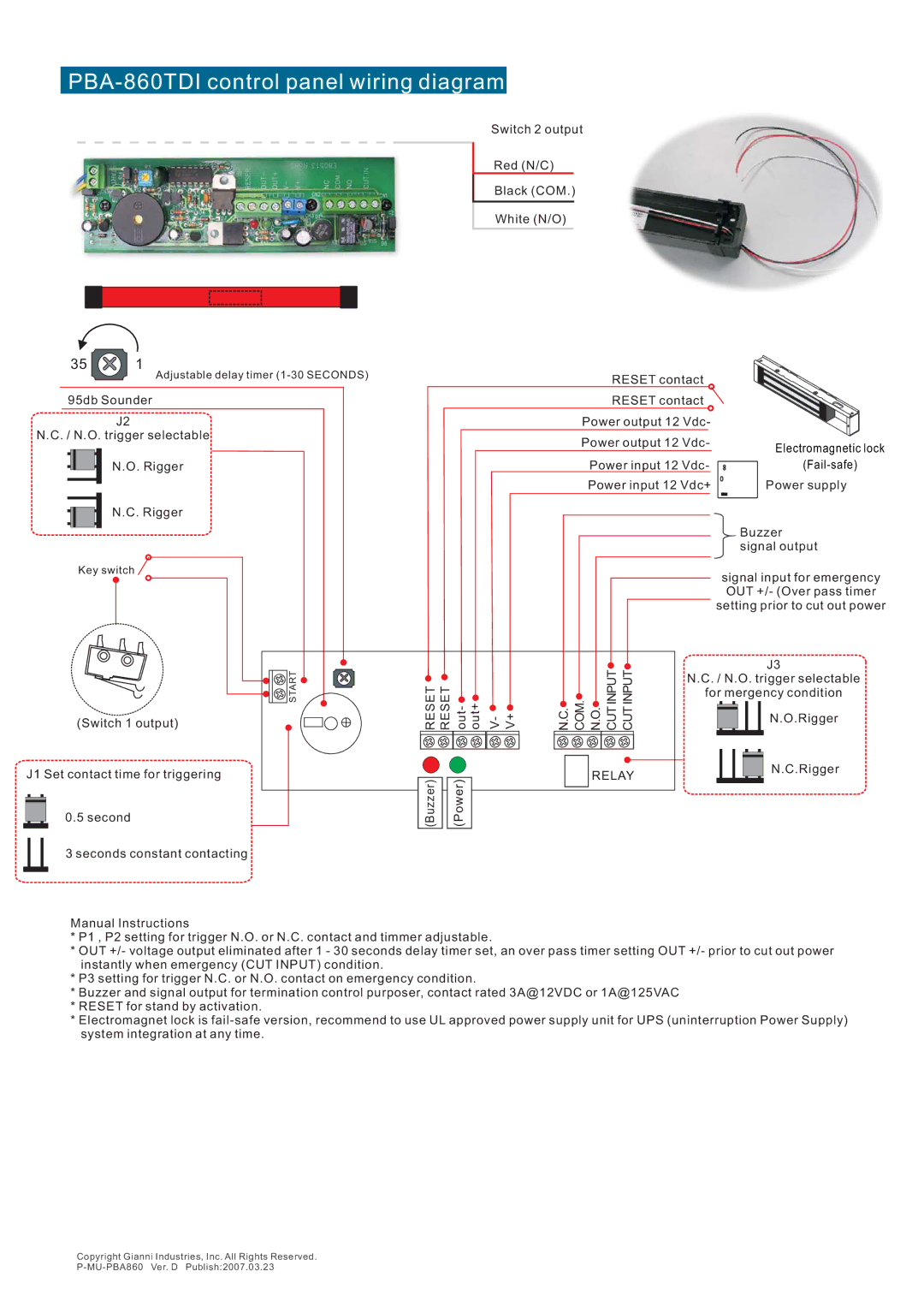
PBA-860TDI control panel wiring diagram
35 ![]() 1
1
Switch 2 output
Red (N/C)
Black (COM.)
White (N/O)
Adjustable delay timer | RESET contact |
|
95db Sounder |
|
|
|
|
|
|
|
|
| RESET contact |
| |
J2 |
|
|
|
|
|
|
|
| Power output 12 Vdc- |
| ||
N.C. / N.O. trigger selectable |
|
|
|
|
|
|
|
| Power output 12 Vdc- |
| ||
|
|
|
|
|
|
|
|
| Electromagnetic lock | |||
|
|
|
|
|
|
|
|
|
|
|
| |
N.O. Rigger |
|
|
|
|
|
|
|
|
| Power input 12 Vdc- | ||
|
|
|
|
|
|
|
|
|
| Power input 12 Vdc+ | Power supply | |
|
|
|
|
|
|
|
|
|
|
|
| GEM |
N.C. Rigger |
|
|
|
|
|
|
|
|
|
|
|
|
|
|
|
|
|
|
|
|
|
|
|
| Buzzer |
|
|
|
|
|
|
|
|
|
|
|
| signal output |
Key switch |
|
|
|
|
|
|
|
|
|
|
| signal input for emergency |
|
|
|
|
|
|
|
|
|
|
|
| |
|
|
|
|
|
|
|
|
|
|
|
| OUT +/- (Over pass timer |
|
|
|
|
|
|
|
|
|
|
|
| setting prior to cut out power |
| START |
|
|
|
|
|
|
|
| N.O. CUTINPUT CUTINPUT |
| J3 |
| RESET | RESET |
|
|
|
|
|
| N.C. / N.O. trigger selectable | |||
|
|
|
|
|
| COM. | for mergency condition | |||||
(Switch 1 output) | out- | out+ | V- | V+ | N.C. |
| N.O.Rigger | |||||
J1 Set contact time for triggering |
|
|
|
|
|
|
|
|
| RELAY |
| N.C.Rigger |
| (Buzzer) |
| (Power) |
|
|
|
|
|
|
| ||
0.5 second |
|
|
|
|
|
|
|
|
|
| ||
3 seconds constant contacting
Manual Instructions
*P1 , P2 setting for trigger N.O. or N.C. contact and timmer adjustable.
*OUT +/- voltage output eliminated after 1 - 30 seconds delay timer set, an over pass timer setting OUT +/- prior to cut out power instantly when emergency (CUT INPUT) condition.
*P3 setting for trigger N.C. or N.O. contact on emergency condition.
*Buzzer and signal output for termination control purposer, contact rated 3A@12VDC or 1A@125VAC
*RESET for stand by activation.
*Electromagnet lock is
Copyright Gianni Industries, Inc. All Rights Reserved.