IDENTIFYING EXTERNAL COMPONENTS
This chapter describes the front panel, rear panel and LED indicators of the Switch
Front Panel
The figure below shows the front panels of the switch.
Front panel view of the Switch
LED Indicators
Comprehensive LED indicators display the conditions of the Switch and status of the network. A description of these LED indicators follows (see LED Indicators)
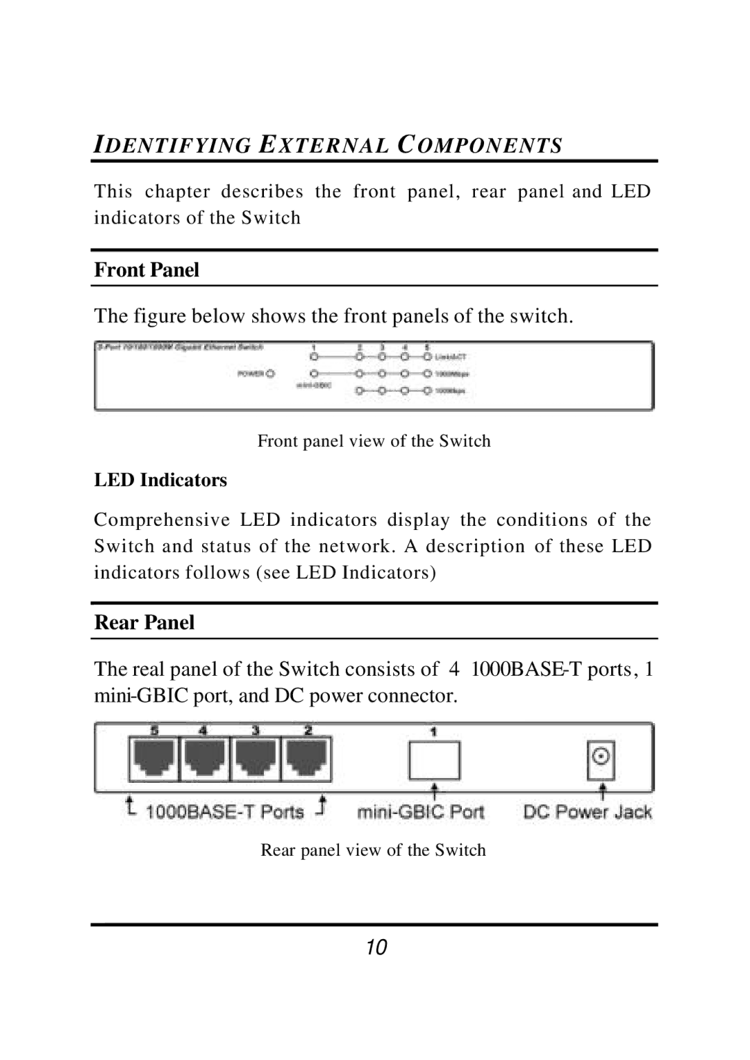
Rear Panel
The real panel of the Switch consists of 4
Rear panel view of the Switch
10