COMPONENTS | TEST PROCEDURE |
| RESULTS |
| |||||||
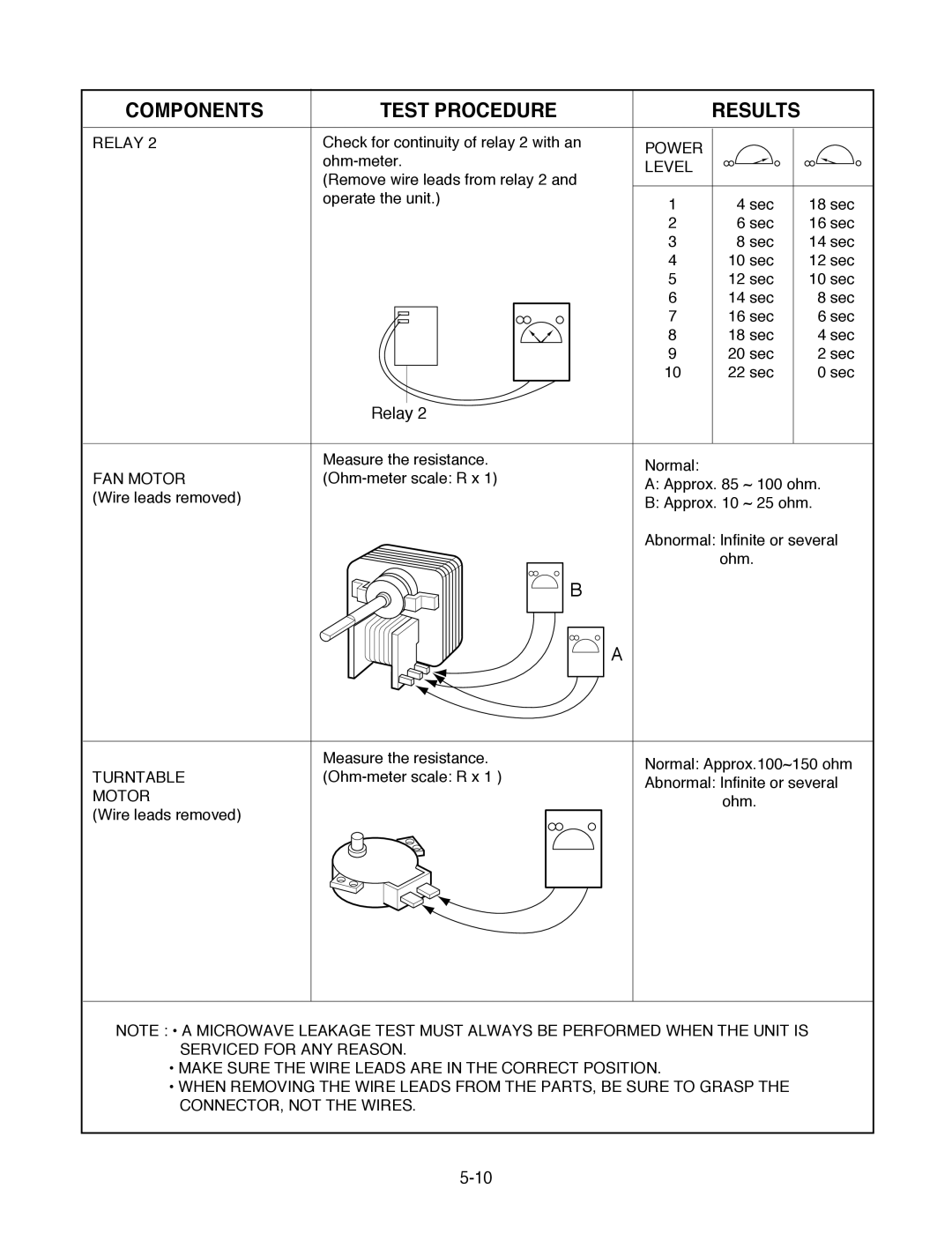
RELAY 2 | Check for continuity of relay 2 with an | POWER |
|
|
| ||||||
|
|
|
| ||||||||
| LEVEL |
|
|
| |||||||
| (Remove wire leads from relay 2 and |
|
|
| |||||||
|
|
|
|
| |||||||
| operate the unit.) | 1 | 4 sec |
| 18 sec | ||||||
|
|
|
|
|
|
|
| ||||
|
|
|
|
|
|
| 2 | 6 sec |
| 16 sec | |
|
|
|
|
|
|
| 3 | 8 sec |
| 14 sec | |
|
|
|
|
|
|
| 4 | 10 sec |
| 12 sec | |
|
|
|
|
|
|
| 5 | 12 sec |
| 10 sec | |
|
|
|
|
|
|
| 6 | 14 sec |
| 8 sec | |
|
|
|
|
|
|
| 7 | 16 sec |
| 6 sec | |
|
|
|
|
|
|
| 8 | 18 sec |
| 4 sec | |
|
|
|
|
|
|
| 9 | 20 sec |
| 2 sec | |
|
|
|
|
|
|
| 10 | 22 sec |
| 0 sec | |
|
|
|
|
|
|
|
| ||||
|
|
|
|
|
|
|
|
| |||
| Relay 2 |
|
|
|
| ||||||
|
|
|
|
|
|
|
|
|
|
| |
| Measure the resistance. | Normal: |
|
|
| ||||||
FAN MOTOR |
|
|
| ||||||||
A: Approx. 85 ~ 100 ohm. | |||||||||||
(Wire leads removed) |
|
|
|
|
|
| |||||
|
|
|
|
|
| B: Approx. 10 ~ 25 ohm. | |||||
|
|
|
|
|
|
| |||||
|
|
|
|
|
|
| Abnormal: Infinite or several | ||||
|
|
|
|
|
|
|
| ohm. |
| ||
|
|
|
|
|
|
|
|
| |||
B
A
| Measure the resistance. |
| Normal: Approx.100~150 ohm |
TURNTABLE |
| ||
| Abnormal: Infinite or several | ||
MOTOR |
|
| |
|
| ohm. | |
(Wire leads removed) |
|
| |
|
|
| |
|
|
|
|
NOTE : ¥ A MICROWAVE LEAKAGE TEST MUST ALWAYS BE PERFORMED WHEN THE UNIT IS SERVICED FOR ANY REASON.
¥MAKE SURE THE WIRE LEADS ARE IN THE CORRECT POSITION.
¥WHEN REMOVING THE WIRE LEADS FROM THE PARTS, BE SURE TO GRASP THE CONNECTOR, NOT THE WIRES.
