Installation | 0.135 in. (3.4 mm) |
|
Do not install equipment approved only for |
|
| |
ardous locations in a hazardous area. |
|
| |
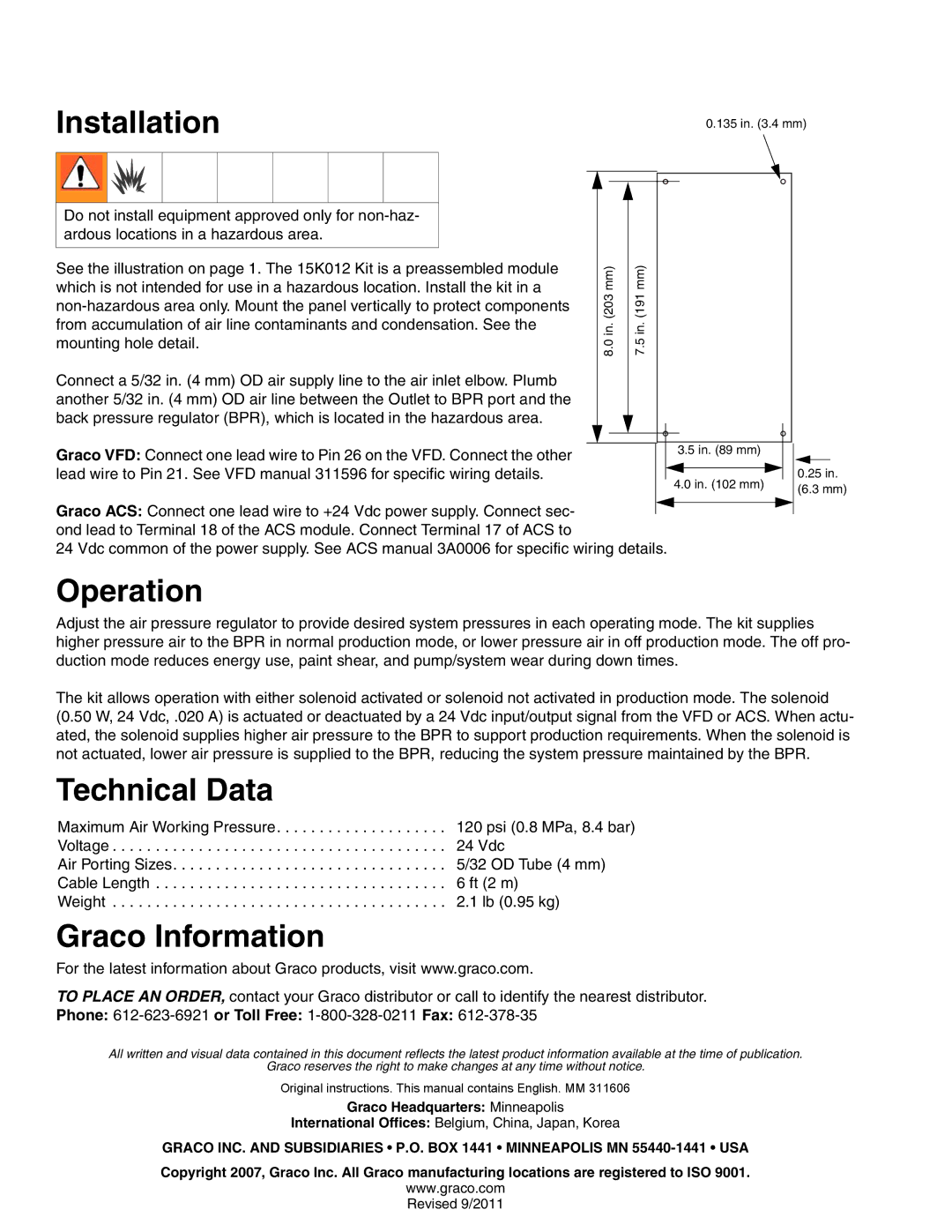
See the illustration on page 1. The 15K012 Kit is a preassembled module | mm) | mm) | |
which is not intended for use in a hazardous location. Install the kit in a | |||
(203 | (191 | ||
|
| ||
from accumulation of air line contaminants and condensation. See the | in. | in. | |
mounting hole detail. | |||
8.0 | 7.5 | ||
| |||
Connect a 5/32 in. (4 mm) OD air supply line to the air inlet elbow. Plumb |
|
| |
another 5/32 in. (4 mm) OD air line between the Outlet to BPR port and the |
|
| |
back pressure regulator (BPR), which is located in the hazardous area. |
|
|
Graco VFD: Connect one lead wire to Pin 26 on the VFD. Connect the other | 3.5 in. (89 mm) | ||
|
| ||
lead wire to Pin 21. See VFD manual 311596 for specific wiring details. |
|
| |
4.0 in. (102 mm) | |||
| |||
Graco ACS: Connect one lead wire to +24 Vdc power supply. Connect sec- ond lead to Terminal 18 of the ACS module. Connect Terminal 17 of ACS to
24 Vdc common of the power supply. See ACS manual 3A0006 for specific wiring details.
0.25in.
(6.3 mm)
Operation
Adjust the air pressure regulator to provide desired system pressures in each operating mode. The kit supplies higher pressure air to the BPR in normal production mode, or lower pressure air in off production mode. The off pro- duction mode reduces energy use, paint shear, and pump/system wear during down times.
The kit allows operation with either solenoid activated or solenoid not activated in production mode. The solenoid (0.50 W, 24 Vdc, .020 A) is actuated or deactuated by a 24 Vdc input/output signal from the VFD or ACS. When actu- ated, the solenoid supplies higher air pressure to the BPR to support production requirements. When the solenoid is not actuated, lower air pressure is supplied to the BPR, reducing the system pressure maintained by the BPR.
Technical Data
Maximum Air Working Pressure. . . . . . . . . . . . . . . . . . . . 120 psi (0.8 MPa, 8.4 bar)
Voltage . . . . . . . . . . . . . . . . . . . . . . . . . . . . . . . . . . . . . . . 24 Vdc
Air Porting Sizes. . . . . . . . . . . . . . . . . . . . . . . . . . . . . . . . 5/32 OD Tube (4 mm)
Cable Length . . . . . . . . . . . . . . . . . . . . . . . . . . . . . . . . . . 6 ft (2 m)
Weight . . . . . . . . . . . . . . . . . . . . . . . . . . . . . . . . . . . . . . . 2.1 lb (0.95 kg)
Graco Information
For the latest information about Graco products, visit www.graco.com.
TO PLACE AN ORDER, contact your Graco distributor or call to identify the nearest distributor. Phone:
All written and visual data contained in this document reflects the latest product information available at the time of publication.
Graco reserves the right to make changes at any time without notice.
Original instructions. This manual contains English. MM 311606
Graco Headquarters: Minneapolis
International Offices: Belgium, China, Japan, Korea
GRACO INC. AND SUBSIDIARIES • P.O. BOX 1441 • MINNEAPOLIS MN
Copyright 2007, Graco Inc. All Graco manufacturing locations are registered to ISO 9001.
www.graco.com
Revised 9/2011
