Graco 
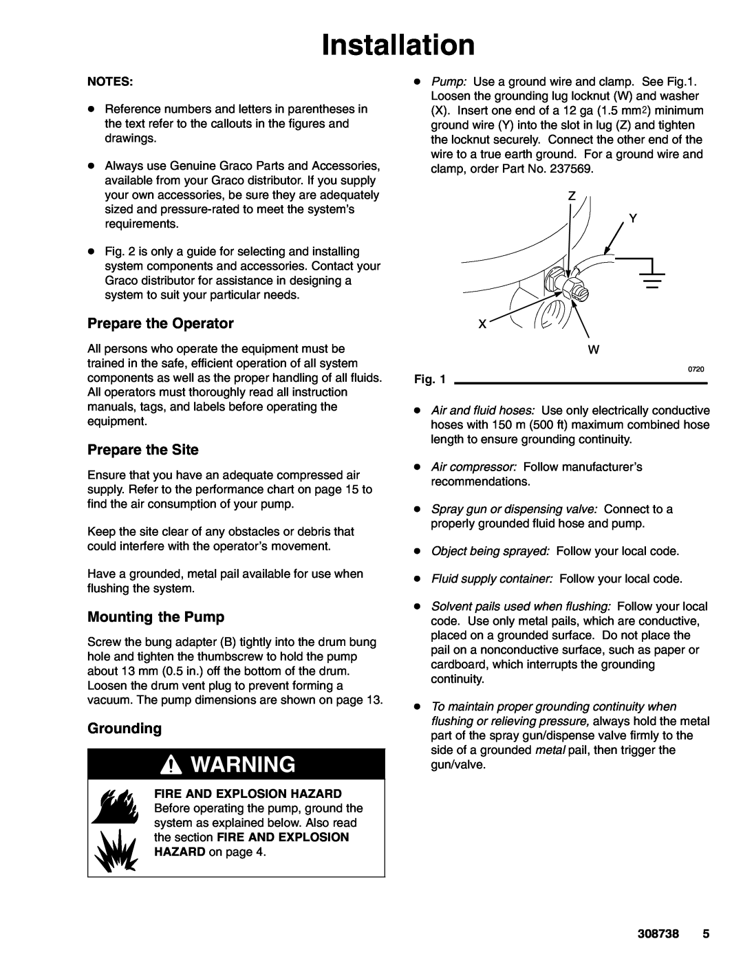
308738C Installation, Prepare the Operator, Prepare the Site, Mounting the Pump, Grounding

Models: 308738C

1 16
Download 16 pages 59.75 Kb
Page 5
Image 5
Installation

Installation

NOTES:

DReference numbers and letters in parentheses in the text refer to the callouts in the figures and drawings.

DAlways use Genuine Graco Parts and Accessories, available from your Graco distributor. If you supply your own accessories, be sure they are adequately sized and pressure-rated to meet the system’s requirements.

DFig. 2 is only a guide for selecting and installing system components and accessories. Contact your Graco distributor for assistance in designing a system to suit your particular needs.

Prepare the Operator

All persons who operate the equipment must be trained in the safe, efficient operation of all system components as well as the proper handling of all fluids. All operators must thoroughly read all instruction manuals, tags, and labels before operating the equipment.

Prepare the Site

Ensure that you have an adequate compressed air supply. Refer to the performance chart on page 15 to find the air consumption of your pump.

Keep the site clear of any obstacles or debris that could interfere with the operator’s movement.

Have a grounded, metal pail available for use when flushing the system.

Mounting the Pump

Screw the bung adapter (B) tightly into the drum bung hole and tighten the thumbscrew to hold the pump about 13 mm (0.5 in.) off the bottom of the drum. Loosen the drum vent plug to prevent forming a vacuum. The pump dimensions are shown on page 13.

Grounding

WARNING

FIRE AND EXPLOSION HAZARD Before operating the pump, ground the system as explained below. Also read the section FIRE AND EXPLOSION HAZARD on page 4.

DPump: Use a ground wire and clamp. See Fig.1. Loosen the grounding lug locknut (W) and washer

(X). Insert one end of a 12 ga (1.5 mm@) minimum ground wire (Y) into the slot in lug (Z) and tighten the locknut securely. Connect the other end of the wire to a true earth ground. For a ground wire and clamp, order Part No. 237569.

Z

Y

X

W

0720

Fig. 1

DAir and fluid hoses: Use only electrically conductive hoses with 150 m (500 ft) maximum combined hose length to ensure grounding continuity.

DAir compressor: Follow manufacturer’s recommendations.

DSpray gun or dispensing valve: Connect to a properly grounded fluid hose and pump.

DObject being sprayed: Follow your local code.

DFluid supply container: Follow your local code.

DSolvent pails used when flushing: Follow your local code. Use only metal pails, which are conductive, placed on a grounded surface. Do not place the pail on a nonconductive surface, such as paper or cardboard, which interrupts the grounding continuity.

DTo maintain proper grounding continuity when flushing or relieving pressure, always hold the metal part of the spray gun/dispense valve firmly to the side of a grounded metal pail, then trigger the gun/valve.

308738 5

Page 5
Image 5
Graco 308738C manual Installation, Prepare the Operator, Prepare the Site, Mounting the Pump, Grounding