A
C
D
B
E
F
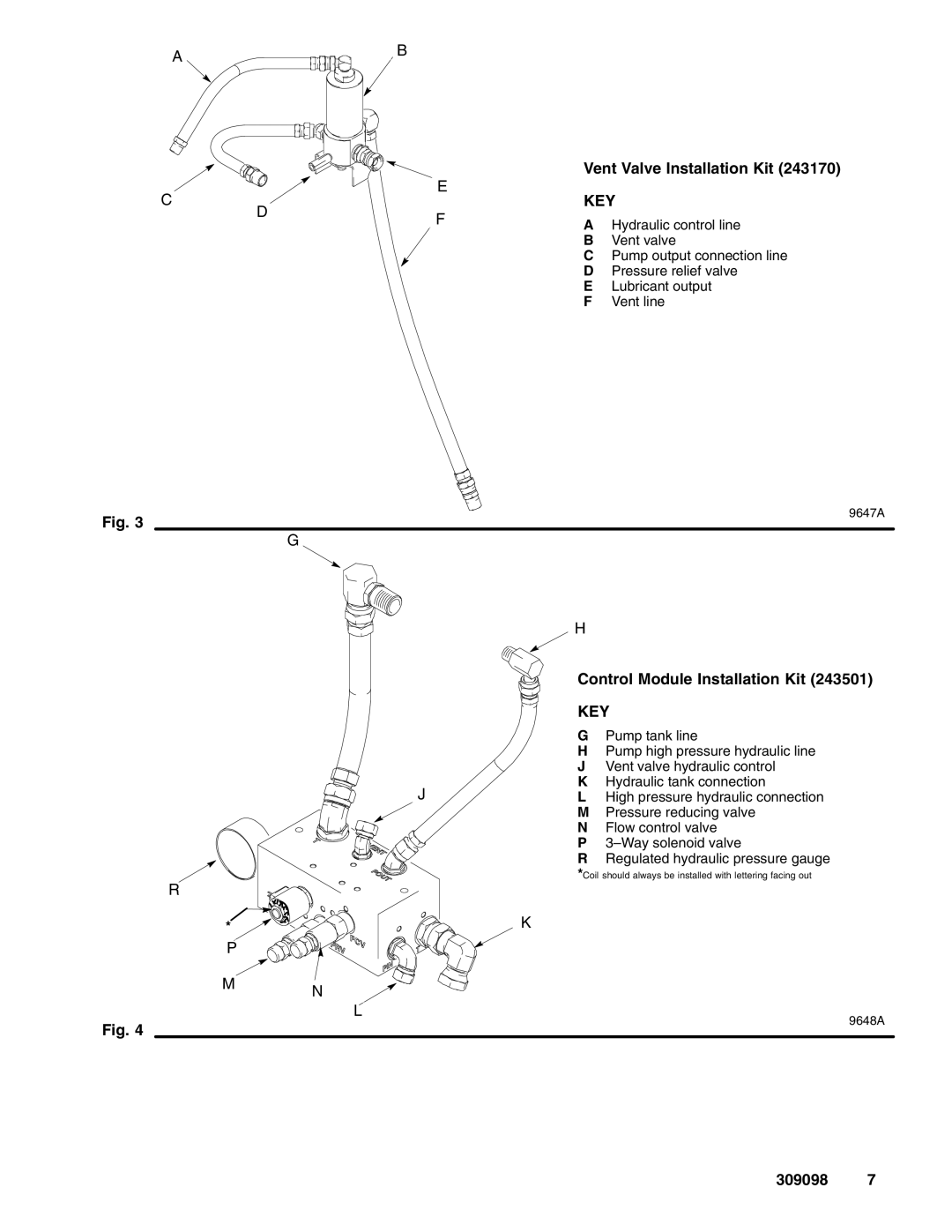
Vent Valve Installation Kit (243170)
KEY
AHydraulic control line
BVent valve
CPump output connection line
DPressure relief valve
ELubricant output
FVent line
Fig. 3
9647A
G
H
J
R
* ![]()
P
M N
L
Fig. 4
Control Module Installation Kit (243501)
KEY
GPump tank line
HPump high pressure hydraulic line
JVent valve hydraulic control
KHydraulic tank connection
LHigh pressure hydraulic connection
MPressure reducing valve
NFlow control valve
P
RRegulated hydraulic pressure gauge
*Coil should always be installed with lettering facing out
K
9648A