Installation (Model 24H989)
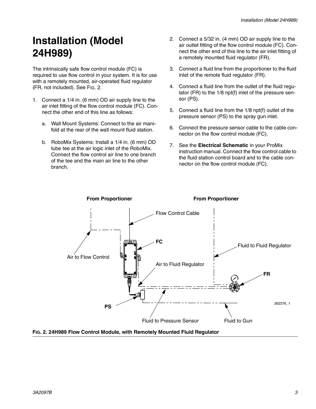
The intrinsically safe flow control module (FC) is required to use flow control in your system. It is for use with a remotely mounted,
1.Connect a 1/4 in. (6 mm) OD air supply line to the air inlet fitting of the flow control module (FC). Con- nect the other end of this line as follows:
a.Wall Mount Systems: Connect to the air mani- fold at the rear of the wall mount fluid station.
b.RoboMix Systems: Install a 1/4 in. (6 mm) OD tube tee at the air logic inlet of the RoboMix. Connect the flow control air line to one branch of the tee and the main air line to the other branch.
Installation (Model 24H989)
2.Connect a 5/32 in. (4 mm) OD air supply line to the air outlet fitting of the flow control module (FC). Con- nect the other end of this line to the air inlet fitting of a remotely mounted fluid regulator (FR).
3.Connect a fluid line from the proportioner to the fluid inlet of the remote fluid regulator (FR).
4.Connect a fluid line from the outlet of the fluid regu- lator (FR) to the 1/8 npt(f) inlet of the pressure sen- sor (PS).
5.Connect a fluid line from the 1/8 npt(f) outlet of the pressure sensor (PS) to the spray gun inlet.
6.Connect the pressure sensor cable to the cable con- nector on the flow control module (FC).
7.See the Electrical Schematic in your ProMix instruction manual. Connect the flow control cable to the fluid station control board and to the cable con- nector on the flow control module (FC).
From Proportioner | From Proportioner |
Flow Control Cable
FC
Fluid to Fluid Regulator
Air to Flow Control
Air to Fluid Regulator
FR
PS
262376_1
Fluid to Pressure Sensor | Fluid to Gun |
FIG. 2. 24H989 Flow Control Module, with Remotely Mounted Fluid Regulator
3A2097B | 3 |
