Installation
•All electrical equipment must only be installed by a qualified electrician.
•Understand and follow your local code and safety regulations for hazardous location wiring of intrin- sically safe circuits.
Dust and Foreign Matter
Avoid having dust or foreign matter enter the flow meter by taking the following precautions:
•Thoroughly flush the fluid supply lines before install- ing the flow meter.
•When installing fittings, make sure that no sealing tape overlaps into the inside of the pipe.
•Install a 100 mesh fluid filter upstream of the flow meter.
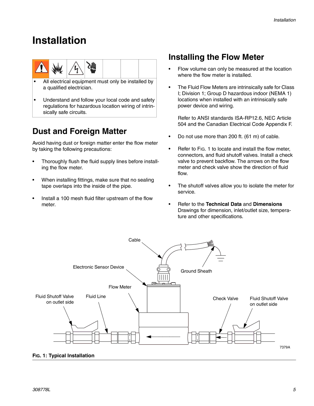
Cable
Electronic Sensor Device
Flow Meter
Fluid Shutoff Valve | Fluid Line |
on outlet side |
|
FIG. 1: Typical Installation
Installation
Installing the Flow Meter
•Flow volume can only be measured at the location where the flow meter is installed.
•The Fluid Flow Meters are intrinsically safe for Class I; Division 1; Group D hazardous indoor (NEMA 1) locations when installed with an intrinsically safe power device and wiring.
Refer to ANSI standards
•Do not use more than 200 ft. (61 m) of cable.
•Refer to FIG. 1 to locate and install the flow meter, connectors, and fluid shutoff valves. Install a check valve to prevent backflow. The arrows on the flow meter and check valve show the direction of fluid flow.
•The shutoff valves allow you to isolate the meter for service.
•Refer to the Technical Data and Dimensions Drawings for dimension, inlet/outlet size, tempera- ture and other specifications.
Ground Sheath
Check Valve | Fluid Shutoff Valve |
| on outlet side |
7379A
308778L | 5 |