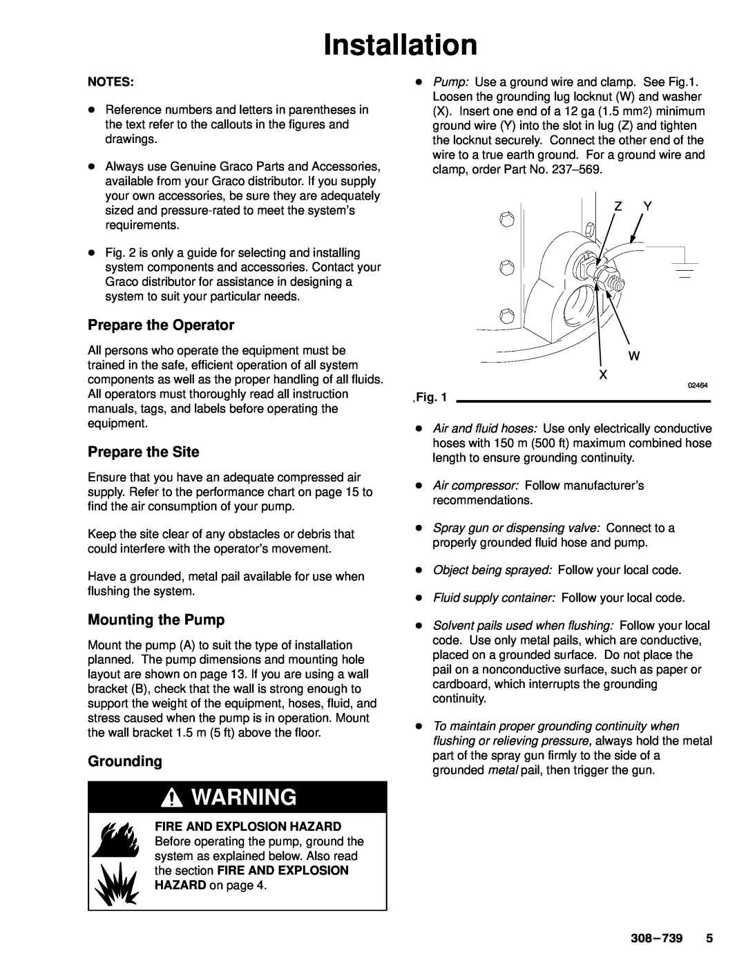
239-327, Series A specifications
Graco is a renowned manufacturer known for its high-quality spray equipment and pumps, catering to both professionals and DIY enthusiasts. Their diverse lineup includes advanced models such as Series A, Series C, Model 237069, Model 289310, and Model 238620, each uniquely engineered to meet various painting and coating applications.The Graco Series A is an outstanding choice for smaller projects. Its lightweight design and portability make it ideal for residential touch-ups, woodworking, and other small-scale applications. This series boasts a simple setup with an easy-to-use spray gun that enables users to achieve a smooth, even finish. Equipped with Graco’s ProConnect technology, Series A allows for quick pump replacement without any tools, ensuring minimal downtime during projects.
The Graco Series C offers enhanced performance and greater versatility for larger applications. This series is designed for professional contractors and serious DIYers, featuring robust construction and advanced technology. With a higher flow rate and pressure capabilities, Series C can handle more demanding projects such as residential and commercial buildings. Additionally, it incorporates SmartControl technology, electronically controlling pressure to provide consistent spray patterns regardless of the fluid being used.
Model 237069 is another exceptional option known for its compact design and efficiency. This electric airless sprayer is perfect for various interior and exterior applications, standing out due to its ease of operation. It features a reversible spray tip, allowing users to quickly clear clogs, and the adjustable pressure settings provide flexibility for different surface textures. Model 237069 is engineered for durability, making it a reliable choice for frequent use.
Model 289310 is engineered for professionals who prioritize speed and precision. This heavy-duty sprayer is equipped with an advanced hydraulic system, which ensures a consistent flow of material. Its larger hopper capacity minimizes the need for frequent refills, allowing users to complete extensive projects faster. Furthermore, the model includes an ergonomic design that reduces fatigue, empowering operators to work longer with comfort.
Lastly, Model 238620 exemplifies Graco’s commitment to innovation in airless technology. This model features an integrated digital display that offers real-time feedback and monitoring, enhancing overall user experience. With its streamlined pump design and advanced filter system, Model 238620 is capable of handling a wide range of coatings, from thin stains to thick latex paints.
In conclusion, Graco's Series A, Series C, Model 237069, Model 289310, and Model 238620 represent the brand’s dedication to quality, performance, and user-friendliness. These models cater to various project sizes and requirements, making them valuable assets for both amateurs and seasoned professionals in the painting industry.
